Simplify Design and Scalability of Automotive Digital Instrument Clusters
投稿人:DigiKey 北美编辑
2016-10-25
Highly integrated system-on-chip (SoC) devices such as NXP i.MX6 application processors offer an effective approach for creating scalable platforms for complex graphics-intensive automotive applications such as instrument clusters. The combination of these SoCs with memory, communications and other peripherals needed in these applications levies significant requirements for ensuring proper voltage, current and power sequencing. For designers, the combination of these automotive SoCs with specialized power management SoCs, such as the NXP MMPF0100, can significantly simplify the design of platforms able to scale from simple instrument clusters for economy cars all the way to high-performance reconfigurable 3D systems for luxury vehicles.
In any vehicle, the dashboard instrument cluster is the driver's primary source of information about the vehicle's status. Yet, the nature of vehicle instrument displays is changing rapidly. Consumers increasingly demand the kind of digital experience in driving that they find in their home entertainment systems and carry with them in their mobile devices. Furthermore, within the vehicle itself, the rapid digitization of vehicle subsystems is significantly changing in the breadth and depth of information available to drivers.
In response to this changing environment, automotive manufacturers are moving beyond traditional analog gauges toward information-rich graphical displays. As part of that evolution, instrument clusters are evolving rapidly with the addition of color 2D and 3D graphics intended to safely provide drivers with information drawn from more sources of digital data. At the same time, manufacturers expect cost-effective solutions for meeting a growing array of requirements for digital dashboards. These dashboards range from designs with more limited functionality in economy trims or vehicle lines to those offering highly advanced customizable displays in luxury offerings (Figure 1).

Figure 1: Vehicle manufacturers are turning to customizable instrument clusters that use 2D and 3D graphics to safely present drivers with a growing wealth of information available from digital subsystems in vehicles. (Image source: Wikimedia Commons/Robert Basic)
For developers, traditional approaches for designing these complex subsystems threaten to fall well behind growing demand. For example, conventional embedded systems designs built around general-purpose processors typically lack the required graphical performance. Furthermore, creating a design able to scale from more limited functionality to fully-realized customizable instruments can be problematic, at best. At a minimum, conventional approaches can require substantial changes in hardware to deliver the incremental functional capability required to scale a basic design to deliver high-end performance. Inevitably, this brute-force approach toward functional enhancement results in the proliferation of highly specialized product designs with potentially incompatible code bases.
Scalable platform
Designs for sophisticated instrument clusters present developers with significant challenges for delivering sophisticated graphics systems able to present complex, fast-changing information in real time. Nevertheless, even these systems typically require more conventional microcontroller functionality for handling the underlying communications and peripherals, such as audio. To balance basic system requirements with those for advanced graphics performance, automotive designers should consider augmenting more familiar MCU-based designs with specialized SoCs able to accelerate execution of graphics and high-level applications code (Figure 2).

Figure 2: To meet demand for high-performance 2D and 3D graphics, automotive engineers augment conventional microcontroller-based designs with specialized SoCs such as NXP i.MX6 processors able to speed processing of application code and graphics operations. (Image source: NXP Semiconductors)
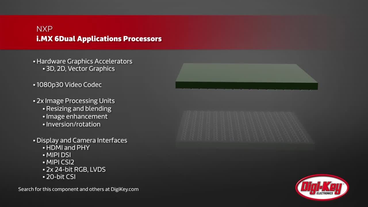
NXP's i.MX6 series of applications SoCs offers a particularly effective solution for automotive instrument cluster designs. Developers can, for the most part, scale an existing i.MX6-based instrument cluster design by dropping in an i.MX6 family member that best matches application requirements for cost and performance. Indeed, the i.MX 6 series is intended to serve as a scalable platform for applications that can require multiple ARM Cortex-A9 processors and integrated graphics processing units (GPUs) for high-performance graphics.
For demanding reconfigurable 3D instrument clusters, the i.MX6DualPlus and i.MX6QuadPlus families offer dual-core and quad-core performance, respectively. Along with the multiple cores running up to 1.2 GHz, these devices include 1 MB of L2 cache, optimized 64-bit DDR3 or 2-channel 32-bit LPDDR2 support, as well as integrated FlexCAN, MLB busses, PCI Express and SATA-2 connectivity. In addition, these devices include LVDS, MIPI display port, MIPI camera port and HDMI v1.4 interfaces typically required in high-end automotive multimedia applications. For less-demanding applications, devices such as the i.MX6Solo offer a lower-cost option that nevertheless combines a single ARM Cortex-A9 core, graphics acceleration, 512 KB L2 cache and 1 x 32 LP-DDR2 memory interface with a full slate of connectivity options.
i.MX6 members offer near drop-in pin compatibility across the series. In practice, however, a few differences in configuration stand in the way of complete drop-in scalability. For example, the i.MX6DualPlus and i.MX6QuadPlus present a few small but distinct requirements at some pins. Quad-core systems connect VDD_ARM_IN pins to the power supply, while dual-core systems typically short those pins and the VDD_ARM23_CAP pins to ground to reduce leakage. Quad-core system designs require placement of external capacitors at VDD_ARM23_CAP pins. Lower-end members of the family introduce a few additional differences in pin configurations. In general, these differences are relatively minor compared to the overall pin compatibility provided across family members.
Graphics acceleration
Members of the NXP i.MX6 series integrate dedicated GPUs designed to accelerate 2D and 3D graphics. For example, the built-in GPU3D core provides a complete high-performance graphics-processing pipeline able to accelerate shading, texturing and rendering of 3D graphics used in a growing array of consumer applications including automotive instrument cluster displays and heads-up displays (Figure 3).

Figure 3: In high-performance members of the NXP i.MX6 family, integrated 2D and 3D graphics-processing units (GPU) use pipeline processing to accelerate graphics operations. (Image source: NXP Semiconductors)
Different members of the i.MX6 series offer different levels of depth in the graphics pipeline, scaling to lower-performance capabilities for lower-cost devices. At the high end of the family, the i.MX6DualPlus and i.MX6QuadPlus offer 2DBLT, eight-layer composition, and four shaders at 720 MHz as well as an embedded prefetch and resolve engine. In contrast, the lower-cost i.MX6Solo supports 2DBLT with a single shader at 528 MHz.
Regardless of underlying processor, developers can take ready advantage of available accelerated imaging resources through a number of industry-standard graphics APIs including OpenGL for embedded systems (OpenGL ES), which is able to take advantage of the i.MX6 GPUs to accelerate 3D graphics. Similarly, the i.MX6 integrated R2D GPU is designed to accelerate OpenVG 2D vector graphics used in graphical user interfaces (GUI) and menu displays, for example.
Design environments such as those from NXP or third parties leverage these APIs to simplify software development of instrument cluster applications. In fact, developers can find software libraries and code that takes full advantage of hardware-accelerated graphics in a way that is transparent to the software engineer. For example, the i.MX 6 series GPU software development kit (SDK) contains working samples and tutorials of simple OpenGL ES 2.0 applications.
Beyond specific graphics code, third-party packages such as the Green Hills Platform for Instrument Clusters, offer comprehensive software solutions built on a scalable family of real-time operating systems (RTOSs) required to meet stringent requirements for low-latency, high-performance automotive digital-display applications.
Complex power requirements
Highly integrated devices such as i.MX6 automotive SoCs help developers meet diverse requirements for scalable instrument cluster designs. Yet, in integrating so much functionality in a single device, these complex devices can present significant power requirements. Furthermore, the broad array of supporting peripherals and interfaces in these designs compounds the problem of ensuring proper power management.
In a dashboard graphics system, developers might need to combine a high-performance i.MX6Dual or i.MX6Quad processor with multiple interfaces and subsystems. These include memory, wireless connectivity, Bluetooth, GPS, audio amplifier, various sensors, camera input, and multiple communication interfaces such as USB, HDMI, SATA, LVDS and mPCIe. Of course, each circuit within the SoC and each supporting module and peripheral within the SoC-based system needs power at specific voltage and current levels.
Furthermore, each power rail running through this complex system needs to be powered up in a specific sequence to ensure proper system boot and proper activation of circuits and modules. Similarly, these circuits and components must be powered down in a specific sequence.
Any deviation from proper power-up or power-down sequences could result in excessive current during power-up, possibly with irreversible damage to the SoC's processor cores, to other SoC integrated modules, or to other components in the system as a whole. As a result, each device and power rail must be monitored for faults during initialization as well as during normal operation. In the automotive industry, in particular, power glitches due to improper initialization or unexpected power failures can quickly lower customer confidence in the product or even escalate to vehicle recalls.
For these complex SoC-based systems, power management based on conventional discrete power devices is impractical at best. Typically, even a single discrete DC-DC switching regulator requires many discrete passive devices to support programming of various parameters such as voltage output, soft-start, frequency, input/output filtering, sequencing delays, closed loop compensation, synchronization, and more. Even a basic low dropout (LDO) regulator requires multiple components for input/output, soft-start, and start-up delay programming.
With the addition of large numbers of external components, discrete power solutions can be bulky and unreliable according to classical parts-count reliability criteria. In terms of size alone, a typical 2-3 A buck regulator can occupy about 100–150 mm2 of pc-board area. A typical 200-300 mA LDO can require about 25 mm2 of pc-board area. Because a typical SoC-based automotive dashboard design could require a half dozen LDOs and the same number of DC-DC converters, vehicle product engineers would find themselves forced to squeeze bulky power packages into dashboard designs intended to remain sleek and size-efficient.
In contrast, a power management SoC such as the NXP MMPF0100, which offers up to six DC-DC converters and six LDOs, enables developers to reduce the size of the BOM, and of the final design itself. In terms of space-savings alone, a MMPF0100 design could fit in about 350 mm2 of pc-board area, while an equivalent discrete solution would need about 800 mm2 of pc-board real estate.
Intended to complement the i.MX6 SoC, the MMPF0100 is designed to supply multiple power rails – initialized in the required sequence – for a complete system including i.MX6 SoCs, memory, and system peripherals (Figure 4). The MMPF0100 features four buck regulators providing up to six independent outputs, one boost regulator, six general purpose LDOs, one switch/LDO combination and a DDR voltage reference to supply voltages for the i.MX6 SoC and peripheral devices.
")
Figure 4: Sophisticated power management SoCs such as the NXP MMPF0100 are able to deliver all the power rails to an i.MX6-based system (A), powering up each rail in a specific developer-programmed sequence (B). (Image source: NXP Semiconductors)
Designers can configure the number of independent buck regulator outputs from four to six. This flexibility allows regulator outputs to operate with higher current capability or to operate as independent outputs for applications that require lower current but more voltage rails. The device's buck regulators can meet supply requirements for the i.MX6 processor cores as well as other low voltage circuits such as IO and memory. Furthermore, built-in dynamic voltage scaling provides controlled supply rail adjustments for the processor cores and other circuitry.
Designed for maximum flexibility, the MMPF0100 provides a series of registers that control the operation of each power device on the SoC (Figure 5). Engineers set the voltage, sequence and other operating parameters by loading the device's on-chip one-time programmable (OTP) memory or by using a special "try-before-buy" mode for prototyping and testing device configuration before OTP memory loading.
| Fuses | Register Name | Register bits | Description |
|---|---|---|---|
| 5:0 | OTP SW1AB VOLT | SW1AB_VOLT[5:0] | SW1AB power-up voltage |
| 6 | – | – | RSVD |
| 11:7 | OTP SW1AB SEQ | SW1AB_SEQ[4:0] | SW1AB power-up sequence |
| 13:12 | OTP SW1AB CONFIG | SW1AB_FREQ[1:0] | SW1AB power-up frequency |
| 15:14 | OTP SW1AB CONFIG | CONFIG[1:0] | SW1A/B/C power-up configuration |
| 18:16 | OTP I²C ADDR | I²C_SLV_ADDR[3.0] | 3 LSBs of the slave address |
| 19 | OTP EN ECC0 | EN_ECC_BANK1 | Enable ECC for OTP fuse bank 1 |
| 25:20 | – | – | ECC check bits for fuse bank 1 |

Figure 5: A sophisticated power management SoC such as the NXP MMPF0100 provides dedicated registers (sample shown at top) for simplified programming (bottom) of on-chip power modules. (Image source: NXP Semiconductors)
Conclusion
By integrating ARM Cortex-A9 cores with dedicated GPUs, the NXP i.MX6 series of automotive application SoCs addresses a growing need for high-performance solutions for graphics-intensive instrument cluster designs. At the same time, these designs present increasingly complex power requirements that limit the effectiveness of conventional discrete power solutions. By combining an i.MX6 SoC with the NXP MMPF0100 power management SoC, developers can rapidly create a highly effective platform for automotive instrument clusters. Furthermore, the range of performance and near drop-in pin compatibility of i.MX6 family members lets developers more easily scale a design from an entry-level system all the way up to a high-performance 3D solution. As a result, developers can limit proliferation of multiple designs and more easily maintain code compatibility across varied product offerings.
免责声明:各个作者和/或论坛参与者在本网站发表的观点、看法和意见不代表 DigiKey 的观点、看法和意见,也不代表 DigiKey 官方政策。