Proper Use of Thermal Derating Curves for Power Modules
投稿人:电子产品
2011-10-04
Designers using modular power converters for their systems know how critical a thermal derating curve is to the success of their design. No offense to marketing people, but the bulleted features on the front page of the datasheet such as those claiming “up to 50-A output current” are a good indication of the general capabilities of the power converter, but can lead the designer down a dark path of no return if used to compare to another manufacturer’s datasheet in selecting a converter that will work in their design. Datasheet front page specs can be different from manufacturer to manufacturer — look closely and understand the conditions at which specifications and claims are made. Dig deeper!
The datasheet
Working with the datasheet, the first requirement is to understand the electrical and thermal performance of a module over the system’s full operating temperature range and, more importantly, exactly how the manufacturer conducted their tests to get the guaranteed minimum and maximum specifications listed in the datasheet.
One must determine the minimum and maximum load currents demanded by the system, plus a comfortable margin, that the module will be able to supply across the entire ambient operating temperature range. This will help guarantee the reliability and also the cost of the final system.¹ (Two of the main things the project manager or your boss has as a top priority).
If ambient temperature is decreased, there will be an allowance for more thermal losses, enabling an increase in output current. By increasing air flow rates, heat loss through convection is increased and again the designer can have increased output current. The power modules internal current-limiting device will ultimately limit the output current at some maximum value.²
Thermal derating curves
The ambient temperature plotted vs. load current gives way to what’s called the thermal derating curve. This curve should always be accompanied by air flow rates and specified nominal input and output voltages (see Figure 1).

This curve now determines the safe operating area (SOA) of a device determined under various air flow rates, input and output voltages, and ambient temperatures. These are conditions at which the internal components are at or below the manufacturer’s maximum operating temperatures.
Thermal testing criteria and measurements
Manufacturers typically derive thermal derating curves from test methodologies³ conducted at their test facilities. Since there is currently no industry standard, these methods can and will vary, but the most common approach is to use a wind tunnel in which a test board is placed, containing the device under test (DUT) soldered in place. Thermocouples (see Figure 2) or thermal imaging cameras (see Figure 3) are used to view the DUT at various input and output voltages, load currents, air flow and direction, module orientation, and air flow blockage of adjacent pc boards and/or components.

Figure 2: Thermocouple attachment options. (Courtesy of Lineage Power.)

The designer considering which manufacturers power module to use must determine if that manufacturer used a thermal camera or thermocouple temperature measurement criteria. If a thermocouple was used, a determination must be made if the measurements were taken at a single location on the DUT or PC board or at an external component “hot spot.” Typically the FET case or tab, control IC or magnetics are the hottest components and should be measured directly if a thermocouple is used. Beware that in using a thermocouple on low mass components, the metal construction of the thermocouple itself will transfer some of the heat away from the part it touches, so it will contribute some error to the exact thermal profile. An “apples-to-apples” comparison in testing criteria must be made in order to make an educated choice as to which power module to use in the system.
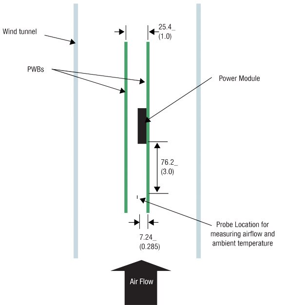
Another important factor to consider is whether the SOA test setup was “restricted.” This means that an adjacent PC board is used in the test to simulate a card-rack environment. This orientation forces air over the power module as it is guided between the boards. The parallel-facing PC board can increase air flow from 1 to 2 m/s (see Figure 4).

Figure 4: Bench-top wind tunnel example (Courtesy of Lineage power)
In an unrestrictive SOA test setup, there is no parallel-facing pc board. Air moves over the module without restricting airflow. The air velocity in this case is decreased as compared to the restricted case.
Lineage Power has some of the best datasheets and a great application note³ regarding thermal derating. Take, for example, the Austin Microlynx II SMT non-isolated board-mounted power module.
Other important details to consider when verifying system performance and reliability
Thermal testing must be done within the final system, in which the power module will reside. Such variables as PC board layout and location of the power module, number of layers of copper and thickness of copper used to thermally conduct heat away from the module, air flow obstructions and turbulence (Note: cooling effectiveness is degraded at higher altitudes due to lower density of air molecules), adjacent components generating heat, PC board spacing in a card rack if used, and possible failure modes.
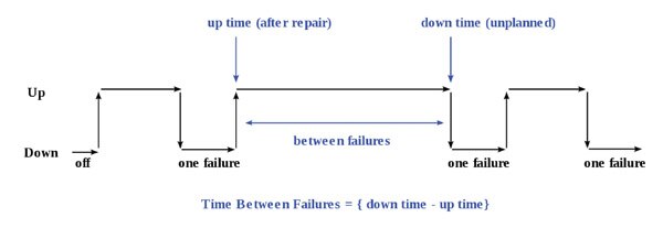
Semiconductor and magnetics maximum operating temperatures must not be exceeded, so adequate testing needs to be done under worst case ambient and air flow conditions. FET’s are particularly susceptible to degradation if operated at or near their maximum junction temperature (Be aware that some manufacturers may set higher operating temperatures of some components that will be closer to the absolute maximum rating — this will have an adverse effect on reliability). The system specification for mean time between failure (MTBF) must be scrutinized and not be degraded by the above potential problem areas (see Figure 5).

Figure 5: MTBF can be calculated as the arithmetic mean (average) time between failures of a system.
Power module efficiency
The efficiency of the power module can greatly affect heat dissipation within the module. A small percentage increase in efficiency can make a tenfold reduction in heat dissipation.
Current sharing of multiple modules
Texas Instruments, for example, does an excellent job in thermal derating in the case of dual modules with current sharing as indicated in its PTH08T250W series datasheet.
Summary
Be aware and educate yourself as to thermal derating test methods used. Note if the device is to be vertically or horizontally mounted. Look for worst-case conditions in testing. Look beyond the datasheet front page and see how the manufacturer has allowed internal component temperatures to approach or reach maximum limits during their tests. Do your homework and you will have a robust design.
References:
- Texas Instruments, “Why is my DC-DC converter too hot?” by Brian Narveson and Geoffrey Jones, Power Electronics, June 2006.
- Technology Blog, “Power Module Thermal Derating Parts I, II and III,” by Jim Beauchamp, June 2009.
- Lineage Power, Application Note, “Thermal characterization process for open-frame board mounted power modules,” July 29, 2009.
免责声明:各个作者和/或论坛参与者在本网站发表的观点、看法和意见不代表 DigiKey 的观点、看法和意见,也不代表 DigiKey 官方政策。


