Active Current Measurement Saves Power, Enhances Safety
投稿人:电子产品
2012-07-05
Current measurement and control are an integral part of any power sensitive system. While most of us have used ammeters to measure current, it is unlikely that budget, space and other practical constraints will allow design engineers to specify an ammeter as part of a finished product; more likely, we will embed some current measurement technique within a given design.
Current measurement has a wide range of uses. Some of these are:
- Making sure a power supply is not damaged by receiving too much current.
- To estimate the rotational speed of a motor (the speed of a motor is directly proportional to the amount of current applied to it).
- To check whether an LED has correct illumination.
- To determine how much current is being applied to a battery pack during charging (so as to prevent overcharging or overheating the batteries).
- To measure the amount of current being applied to a circuit from the battery pack, enabling estimation of the battery life.
This article discusses techniques and devices that can be used when measuring current flow. Both microscopic (nanoampere) and macroscopic (hundreds of amperes) needs are addressed here and can be used as a starting point in the journey to satisfy your specific design needs.
Simple and straightforward
The simplest and most direct way to measure current is through the use of Ohm’s Law. If a known value resistance is in series with a load, the voltage across it will be directly proportional to the current. This means that a highly accurate resistor should yield a highly accurate current measurement.
The downside to this approach is that any resistance in series with a load limits the current to the load, and is itself a voltage drop. What’s more, it is going to dissipate power. This may or may not be a problem depending on your constraints and how you design your measurement stage.
Low power and battery-powered designs don’t want to waste any energy so resistance values need to be very low. In addition, space is usually a constraint with these types of designs, so in such cases, a compact and accurate resistor-based measurement technique is a good simple solution, especially if it can be ground-side referenced.
Current sensors, then, are electronic circuits that monitor the current flow by measuring the voltage drop across a resistor placed in the current path (while other technologies exist, such as magnetic, everything discussed here is limited to shunt resistor current measurement). The current sensor outputs either a voltage or a current that is proportional to the current through the measured path.
Since resistive measurements are series measurements, sensor devices can go anywhere in the series loop where the current flows through. This means that typically they can be applied to the positive terminal of the power supply, or the negative terminal (Figure 1).

Figure 1: Both high-side and low-side measurement techniques can be used, but note the inverted current/voltage waveform when using high side measurements referenced to ground.
Since most designers chassis ground to the negative power supply terminal, it can be undesirable to raise the ground floor with a variable voltage level related to current draw. This may be true for large voltage swings, but is not an issue if voltage levels are very low.
For example, a low power embedded microcontroller may draw 10 microamperes while in sleep mode, and draw 5 milliamperes while in active mode. A compact and accurate surface-mount resistor such as the Panasonic ERJ-6BWFR010V (a one percent, 0.25 W, 0805 packaged 0.01 Ω resistor), will only raise the ground floor 50 µV at full-scale 5 mA load. This is well below any level that will affect logic signals.
The 50 µV full-scale voltage level will need to be amplified to the A/D’s full-scale range to get best resolution. Also, either a zero offset adjustment or software calibration technique may be needed.
A benefit of high-side current measurement is that it is usually much quieter from a noise point of view. Typically, the high side, especially the raw battery side, is regulated and filtered before being applied to the load. It doesn’t see the cumulative clocks and high-frequency noise that the ground lines can see.
Also, because a current sense can be applied before a regulator, a slight voltage variation due to the sense resistor’s presence will not translate into any voltage drops across your system. But, because of the inverted current/voltage curve of a high-side sense resistor, an inverting differential amplifier should be used to bring the sense waveform back to where the resulting voltage is directly proportional to the current flow (Figure 2).

Figure 2: A differential inverting amplifier design can transform the high-side waveform to a more familiar voltage for A/D converters.
Note, if using high-side sensor before a regulator, make sure the measurement points are not higher than the supply voltage of the op amps. Also, use snubbers and protection circuits when inductive flyback spikes can be generated as these will kill sensitive op-amp and instrumentation-amplifier inputs.
When using a sense resistor before a regulator, you will need to use power calculations to accurately determine the current through the load at a specific voltage.
For example, say you have a 12 V battery connected through a series resistor going to a voltage regulator (Figure 3). Our load to be measured can vary from 1 to 100 mA at the 5 V level.

Figure 3: When using high-side current sense before a regulator, adjust current readings based on power calculations.
The current flowing from the 12 V source to supply that 0 to 100 mA is actually 0 to 41.6 mA. When doing high-side measurements this way, plan for the adjusted current. Also, factor in the loss of the regulator. The type of regulator and its efficiencies will affect performance.
The sense resistor can work well for low current applications but requires the measurement circuitry to be electrically connected to the source and load. There are times when electrical isolation is desired or demanded by regulations and customers.
A technique that can be employed for low current measurements, and which provides galvanic isolation, is to use a linear opto-isolator like the IL300 from Vishay. This part is like a digital optoisolator with a linear current transfer curve. By using an isolated feedback detector as well as a primary detector, the IL300 couples AC and DC signals with 0.01 percent servo linearity (Figure 4).

Figure 4: Linear optoisolators can be used for small or even large current measurements and provide galvanic isolation. Drive circuitry comes from the non-isolated side, but measurement is applied to the isolated side.
Because it is using infrared light as the coupling medium, the IL300 achieves over 5,000 V isolation. The biasing circuitry will be connected on the non-isolated side, but the measurements can take place fully isolated.
Similar parts come from CP Clare with its photovoltaic LOC111PTR opto-coupler and Avago with its HCNR200 device. Other linear optoisolator devices and families from Vishay, Avago and Clare are readily available for off-the-shelf shipment from DigiKey.
More current
Not every current sense application is low powered. Current flow is also a very useful tool to help us design fault detection and failsafe circuits. For example, a motor controller can use a current sensor to detect a fault such as a stuck motor. This protects the circuitry from trying to force too much current into a motor that just won’t start. Running overloads also can be sensed in this way.
Motors come in all sizes so, as an example, we will use a medium size motor that can draw 10 to 25 A. Here, a current sensor can use resistive techniques as well as Hall Effect techniques, which have the advantage of galvanic isolation between the sensed circuit and the measuring circuit that can add another layer of protection.
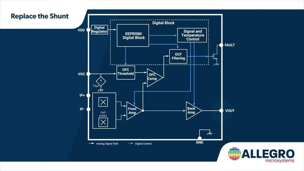
A typical current sensor for this range could be, for example, an Allegro ACS711ELCTR-25AB-T (Figure 5). This part can sense ±25 A, which could be useful for a bi-directional motor application where current can flow either way. This part also uses an internal Hall Effect with a copper conduction path in close proximity to the sensor. It provides an inherent 100 V isolation barrier and can be used for both AC- and DC-sensing applications.

Figure 5: Using an embedded Hall Effect sensor in close proximity to the very-low-resistance current path provides inherent isolation while providing integrated functionality including temperature compensation and fault detection.
You should note the very low 1.2 mΩ resistance allows the small-sized SOIC 8-pin package to pass 25 A with only 0.75 W of power dissipation needed. The close proximity of the amplifier with the sense elements helps reduce noise (especially with the integrated electrostatic shield). Overcurrent fault detection is also built in and the part is factory-trimmed for higher accuracy (± 5percent).
Designed to work with 3.3 or 5 V systems, stepped resolution of 55 mV/A can easily interface to most A/D’s and only draws 4 mA of current while active. A similar part with a higher accuracy (at the expense of a little more power draw) is the Melexis MLX91206LDC-CAHB Triaxis sensor.
Keep in mind that the Melexis part is specified as milliTesla ranges and with an output in millivolts per milliTesla. But, in a similar SOIC 8-pin package, the Melexis part provides a ±0.75 percent accuracy using 9 mA for 5 V systems based on a technique the company calls Triaxis (Figure 6). This uses an embedded magneto concentrator on the CMOS die requiring an extra step at fab. Like the Allegro part, the Triaxis sensor integrates a lot of useful functions such as programmable offsets, gains, clamping levels, and diagnostics.

Figure 6: The Triaxis approach uses a deposited magnetic concentrator on the die which helps accurately measure the current flowing through the close proximity current path.
Power dissipation
Some applications use so much current, that power dissipation in a sense resistor can be a critical issue. As an example, consider a renewable energy battery charger that will need to measure up to 250 A of current coming in from a solar or wind power array.
If we will be measuring current using a microcontroller with an A/D running at 3.3 V, we may want to design our circuit to generate a voltage swing of, 0 to 2.56 V corresponding to a 0 to 256 A current measurement. This makes software easy since each millivolt read is 1 A. A 10 bit A/D would yield a 0.25 A resolution.
If we use a 0.01 Ω resistor like the TE Connectivity 7-1625971-5 in series with the charge current going to the battery, we should expect to see a 0 to 2.56 V drop across the resistor corresponding to a current swing of 0 to 256 A. The 2.56 V output needs no amplification and is a good value that can be fed into most A/D converters (if low-side biased).
Even at 0.01 Ω, 250 A, this resistor will be dissipating 625 W, enough to allow it to be used as a hot-water heating element in a small coffee pot. This part could be used to measure a lower current, for instance up to 50 A, where it would still dissipate 25 W of power. That’s still a lot of power.
A better approach for this application may be the Vishay WSBS8518L1000JK, which is only 0.0001 Ω and can handle up to 36 W (Figure 7). Note though that you will only see a voltage swing of 0 to 25.6 mV, which means you will need an op amp, instrumentation amplifier, or microcontroller with a gain stage to be able to achieve the highest possible resolution. Also note that even at 0.0001 Ω, at full load you will still be dissipating 6.5 W.

Figure 7: The very small 0.0001 Ω resistance allows this shunt to handle up to 36 W with a 5 percent tolerance.
The above mentioned examples are 5 percent tolerance parts and increased tolerances will provide increased accuracies. A part like the Ohmite TGHGCR0010FE makes an ideal current sensor for a 1 percent tolerance up to 100 W. The thick-film technology has a low-temperature coefficient of only ±60 ppm and is designed to exhibit non-inductive properties.
Note that the TGHG series is designed for use with proper heatsinking. The maximum baseplate temperature of the resistor must be monitored and kept within specified limits to establish the power rating. Ohmite recommends that you attach a thermocouple to the side of the baseplate of the resistor. Ohmite also provides a training module for its Current Sensing Resistors on DigiKey’s website.
Other issues and techniques
You may have realized by now that even 1/100 of an ohm resistance at these current levels can dissipate large amounts of power and introduce error voltages. Key to improving accuracy is to measure the voltages across the shunt or sensor resistors directly before it makes contact with the rest of the current loop (Figure 8). This may seem like redundant wiring, but it can preserve accuracy since the voltage across the sensor will be measured without any contact loss due to even very small amounts of resistances.

Figure 8: It may seem redundant, but direct connect wires across the current-sense resistor help assure accuracy since voltage drops due to contact resistances in the high-current paths won’t introduce error voltages.
This means that even if there are voltage drops anywhere in the current loop, the measured voltage across the sensor will still provide an accurate representation of the true current flowing through the circuit.
In summary
Electric current is an important physical quantity and its measurement is required in many applications in the industrial, automotive, or household fields. As stated by Ohm’s Law, there is a voltage drop across any resistance when current is flowing. In a current-sensing resistor, calibrated resistance senses the current flowing through it in the form of a voltage drop, which is detected and monitored by control circuitry.
This article has explored different technical solutions to measure currents that are found on the market, and has discussed both low-current and high-current applications. All parts, tutorials, datasheets, development kits, and training materials referenced here are available on the DigiKey website (use the links provided).
免责声明:各个作者和/或论坛参与者在本网站发表的观点、看法和意见不代表 DigiKey 的观点、看法和意见,也不代表 DigiKey 官方政策。