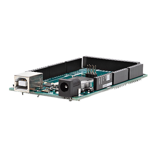
制造商零件编号 A000067
ARDUINO MEGA2560 ATMEGA2560
Arduino
所订产品一般在 4天 内送达中国,具体时间取决于收货地点。
订单金额满 $100 USD免运费发送至中国。 所有少于 $100 USD的订单将收取$30 USD的运费。
按照《2010 年国际贸易术语解释通则》规定,如果预付并总算,则采用 CPT 结算方式;如果是同承运人结算,则采用 FCA Thief River Falls 结算方式
客户承担所有应缴纳的关税、经纪费等各项税费
针对合格机构和企业提供的信用帐户
电汇预付
![]()
![]()
![]()
![]()
更多来自全授权合作伙伴的产品
下单后,从合作伙伴发货平均需要时间 1-3 天,也可能产生额外运费。可能另外收取运费。 实际发货时间请留意产品详情页、购物车和结账页面上的说明。
国际贸易结算方式:CPT(交货时支付关税、海关费用和适用 VAT/应付税金)
有关详情,请访问帮助和支持
License: Attribution Non-commercial
Background
I was working on a circuit this weekend that was controlling a DC motor-driven linear actuator. While working through various designs for the circuit I remembered the MOSFET circuit I had learned in my motors class last year, the H-Bridge.
Named after the shape of the circuit, the H-bridge is a circuit that allows for a motor to have a varying speed and direction without having to actually change wires around! The chip I used for this project was a "TB6612FNG MOTOR DRIVER BOARD" from Digi-Key.com. This board is a breakout for the TB6612FNG that allows for prototyping on a breadboard and can control motors with low-current applications.
What do you need to try this out?
For this project you will need:
What do you need to do to get started?
The H-bridge is a fairly easy circuit to understand, and the video above definitely explains the device in greater detail. Below is the circuit layout of the H-Bridge:
The general rule is that you only power 2 switches at a time, on diagonal sides. So powering S1 and S4 would cause current to flow left to right in the motor. Alternatively, you can power S3 and S2 while opening S1 and S4 and the current will flow right to left in the motor, causing a spin in the opposite direction as before. If you power just one of the switches, the motor will stop moving and coast. Finally, if you power S1+S2 or S3+S4 you will short the power supply and possibly damage other components, so avoid that always!
For the Arduino, I used this code below:
int in1A = 3;
int in2A = 4;

void setup()

{
  // Set all the motor control pins to outputs
  pinMode(in1A, OUTPUT);
  pinMode(in2A, OUTPUT);
}

void loop() {
  analogWrite(2, 45);
  //Set motor forward
  digitalWrite(in1A, HIGH);
  digitalWrite(in2A, LOW);
  delay(2000);
  //Stop motor
  digitalWrite(in1A, LOW);
  digitalWrite(in2A, LOW);
  delay(2000);
  //Set motor reverse
  digitalWrite(in1A, LOW);
  digitalWrite(in2A, HIGH);
  delay(2000);
  //Stop motor
  digitalWrite(in1A, LOW);
  digitalWrite(in2A, LOW);
  delay(2000);
}
The motor controller I used only had 2 control pins rather than 4 and a speed pin. It was kind of like having only control over the S1 and S3 switches, with the controller automatically selecting S2 and S4 to produce valid motion. You can see in my code how I flip which pins are high and which are low in order to change the direction of the motor.
I hope you learned something from this circuit! I know it's one of my favorites for directional current control for motors and actuators!
所订产品一般在 4天 内送达中国,具体时间取决于收货地点。
订单金额满 $100 USD免运费发送至中国。 所有少于 $100 USD的订单将收取$30 USD的运费。
按照《2010 年国际贸易术语解释通则》规定,如果预付并总算,则采用 CPT 结算方式;如果是同承运人结算,则采用 FCA Thief River Falls 结算方式
客户承担所有应缴纳的关税、经纪费等各项税费
针对合格机构和企业提供的信用帐户
电汇预付
![]()
![]()
![]()
![]()
更多来自全授权合作伙伴的产品
下单后,从合作伙伴发货平均需要时间 1-3 天,也可能产生额外运费。可能另外收取运费。 实际发货时间请留意产品详情页、购物车和结账页面上的说明。
国际贸易结算方式:CPT(交货时支付关税、海关费用和适用 VAT/应付税金)
有关详情,请访问帮助和支持
谢谢!
敬请关注收件箱中的 DigiKey 新闻与更新!
请输入电子邮件地址

