欢迎阅读关于Synergy软件平台的另一篇指南。本指南将介绍如何设置多个线程来轮询多个传感器,将这些传感器的信息发送到另一个线程进行处理,最后将处理后的信息发送到输出线程。本指南将运用本系列先前指南中的概念,但旨在提供独立设置项目演示的指导。这是关于使用DK-S124的教程,该开发板可从DigiKey获取,型号RTK7DKS124S00002BU,瑞萨电子| 开发板、套件、编程器 | DigiKey。
本指南包括示例程序概述、e2 studio中的项目设置/配置流程、带注释的项目源代码,以及程序输出和结论。一如既往,下方附有实用链接。
开发板用户手册:《DK-S124快速入门指南》(renesas.com)
Synergy软件包用户手册:瑞萨Synergy™软件包(SSP)| Renesas
程序概述
假设有一个如下图的简单程序结构。
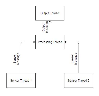
在此程序中,两个传感器线程轮询独立的传感器,并将数据作为“传感器消息”发送到第三个线程进行处理,处理后的数据作为“输出消息”发送。此示例可轻松扩展至更多传感器线程,甚至根据需要支持不同的传感器消息类型。
为简化实现,示例中将模拟传感器数据,处理过程非常轻量,输出通过UART完成。将使用的Synergy软件平台关键特性是支持多线程的瑞萨消息框架。
e2 Studio 的设置 / 配置
打开e2 studio并创建一个新的Synergy C项目。本指南将项目命名为MultiThreadMessageGuide。确保选择正确的设备(DK-S124使用R7FS124773A01CFM),并选择BSP作为项目模板。若对这些步骤不熟悉,请参阅《在DK-S124上配置和使用UART接口》指南,了解完成e2 studio初始设置后如何创建项目。
新项目打开后,进入项目配置文件的线程选项卡。由于本程序有4个线程,必须创建4个线程。依次创建“sensor_thread1”、“sensor_thread2”、“computation_thread”和“output_thread”。接下来,将添加所需的线程栈。由于我们有4个线程,每个线程通常需要占用1024字节的RAM,而在此配置下DK-S124仅有3960字节可用空间,因此需要略微缩减其中一个线程的栈大小。于是,将输出线程的"栈大小"属性从1024字节调整为800字节。
本项目仅需两个线程栈:消息框架和UART驱动。从技术上讲,消息框架可以添加到任何非HAL/通用线程中。本指南将其添加到计算线程,因为无论传感器线程如何变化,该线程始终存在。显然,UART驱动将置于输出线程,因为该线程会直接使用它。
将消息框架线程栈添加至计算线程(添加线程栈>框架>服务>消息框架)。本指南中其所有默认选项均可正常工作。接着添加UART驱动线程栈(添加线程栈>驱动>连接>UART驱动)。与先前指南不同,“用户定义的UART回调函数"将保留为"user_uart_callback”,该函数用于判断UART设备何时完成写入。与之前指南类似,接收、发送和发送结束中断优先级必须从"禁用"改为0到2之间的某个值。若对这些步骤不熟悉,请参阅《在DK-S124上配置和使用UART接口》获取添加和配置线程栈的详细说明。
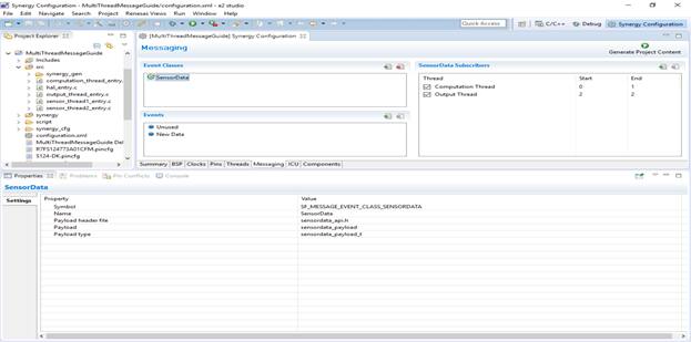
现在需要通过消息标签页配置消息框架。进入消息标签页,新建名为SensorData的事件类。其余字段将自动填充。若对此步骤不熟悉,请参考《在Renesas DK-S124上使用ADC和ThreadX RTOS消息框架》的"设置消息框架"章节。
本示例中,即使输出线程也仅使用此事件类。可能该设备正在进行传感器融合,仅对外暴露一组数值。但本示例可根据需要扩展为使用不同事件类处理输出数据。
最后,需为SensorData事件类添加订阅者。由于存在多个订阅者,将使用事件实例字段进行区分。点击新建订阅者按钮,下拉选择"计算线程",并填写"起始"0和"结束"1。这意味着计算线程将接收header.event_b.class_instance值介于0到1之间的所有SensorData消息。这些消息将由传感器线程生成。接着,再添加一个订阅者。通过将“开始”和“结束”字段均填写为数字2,将输出线程订阅到所有类实例值为2的SensorData消息。计算线程将生成这些消息。注意,本可以使用单独的事件类来实现此目的,但通过这种方式可以展示如何利用类实例值来定向消息。
点击生成项目内容按钮,此时您的屏幕应显示如下:
注释源代码
首先,必须创建并填充sensordata_api.h文件。右键单击MultiThreadMessageGuide项目的“src”目录,选择新建>头文件。将名称设为sensordata_api.h。该文件将详细说明应用程序所用消息的结构。
在本示例中,假设每个传感器都有几个16位数据的通道。这些可能是来自加速度计的不同轴,或来自一系列传感器的多个温度值。每个传感器线程将发布此类型的消息。
sensordata_api.h
#ifndef _SENSORDATA_API_H_
#define _SENSORDATA_API_H_

#define NUMCHANNELS (uint8_t)10

#include "sf_message_api.h" //this is a message, so the message api is needed

typedef struct sensordata_payload_s
{
    sf_message_header_t header; //every message must include a header of this type
    uint8_t sensorchannel[NUMCHANNELS]; //suppose there are a number of channels from the sensor
    uint16_t sensordata[NUMCHANNELS]; //this is the data from each channel
} sensordata_payload_t; //This name is specified in "Event Class" properties as "Payload Type"

#endif
接下来是sensor_thread1.c和sensor_thread2.c:
sensor_thread1_entry.c
#include "sensor_thread1.h"
#include "sensordata_api.h"

/* Sensor Thread 1 entry function */
void sensor_thread1_entry(void)
{
    //Message init
    //sending sensordata init
    sf_message_header_t * pPostBuffer; //pointer for the buffer that must be acquired
    sf_message_acquire_cfg_t acquireCfg = {.buffer_keep =false}; //do not keep the buffer, other threads need it
    ssp_err_t errorBuff; //place for error codes from buffer acquisition to go
    sf_message_post_err_t errPost; //place for posting error codes to go
    sf_message_post_cfg_t post_cfg =
    {
      .priority = SF_MESSAGE_PRIORITY_NORMAL, //normal priority
      .p_callback = NULL //no callback needed
    };
    sensordata_payload_t * pDataPayload; //pointer to the receiving message payload

    while (1)
    {
        //send as message if possible
        errorBuff = g_sf_message0.p_api->bufferAcquire(g_sf_message0.p_ctrl, &pPostBuffer, &acquireCfg, 0);
        if (errorBuff==SSP_SUCCESS)
        {
            pDataPayload = (sensordata_payload_t *) pPostBuffer; //cast buffer to our payload
            pDataPayload->header.event_b.class_code = SF_MESSAGE_EVENT_CLASS_SENSORDATA; //set the event class
            pDataPayload->header.event_b.class_instance = 0; //set the class instance
            pDataPayload->header.event_b.code = SF_MESSAGE_EVENT_NEW_DATA; //set the message type

            for (uint8_t temp=0; temp<NUMCHANNELS;temp++) pDataPayload->sensordata[temp] = temp; //fill the payload with dummy data
            for (uint8_t temp=0;temp<NUMCHANNELS;temp++) pDataPayload->sensorchannel[temp] = temp;
            g_sf_message0.p_api->post(g_sf_message0.p_ctrl, (sf_message_header_t *) pDataPayload,
                                      &post_cfg, &errPost, TX_WAIT_FOREVER); //post the message
        }
        tx_thread_sleep (205);
    }
}
sensor_thread2_entry.c
#include "sensor_thread2.h"
#include "sensordata_api.h"

/* Sensor Thread 2 entry function */
void sensor_thread2_entry(void)
{
    //Message init
    //sending sensordata init
    sf_message_header_t * pPostBuffer; //pointer for the buffer that must be acquired
    sf_message_acquire_cfg_t acquireCfg = {.buffer_keep =false}; //do not keep the buffer, other threads need it
    ssp_err_t errorBuff; //place for error codes from buffer acquisition to go
    sf_message_post_err_t errPost; //place for posting error codes to go
    sf_message_post_cfg_t post_cfg =
    {
      .priority = SF_MESSAGE_PRIORITY_NORMAL, //normal priority
      .p_callback = NULL //no callback needed
    };
    sensordata_payload_t * pDataPayload; //pointer to the receiving message payload

    while (1)
    {
        //send as message if possible
        errorBuff = g_sf_message0.p_api->bufferAcquire(g_sf_message0.p_ctrl, &pPostBuffer, &acquireCfg, 0);
        if (errorBuff==SSP_SUCCESS)
        {
            pDataPayload = (sensordata_payload_t *) pPostBuffer; //cast buffer to our payload
            pDataPayload->header.event_b.class_code = SF_MESSAGE_EVENT_CLASS_SENSORDATA; //set the event class
            pDataPayload->header.event_b.class_instance = 1; //set the class instance
            pDataPayload->header.event_b.code = SF_MESSAGE_EVENT_NEW_DATA; //set the message type

            for (uint8_t temp=0; temp<NUMCHANNELS;temp++) pDataPayload->sensordata[temp] = temp+20; //fill payload with dummy data
            for (uint8_t temp=0;temp<NUMCHANNELS;temp++) pDataPayload->sensorchannel[temp] = temp+17;
            g_sf_message0.p_api->post(g_sf_message0.p_ctrl, (sf_message_header_t *) pDataPayload,
                                      &post_cfg, &errPost, TX_WAIT_FOREVER); //post the message
        }
        tx_thread_sleep (100);
    }
}
在本示例中,这两个线程几乎相同;但在实际应用中,两个传感器的轮询方式可能不同。可能一个传感器是i2c接口,另一个只是GPIO传感器,或者其中一个使用ADC读取。因此,设置两个传感器线程是合理的。本示例中,线程有两个关键区别:tx_thread_sleep时间不同以模拟不同刷新率的传感器,虚拟数据不同以模拟不同的传感器值。
接下来是计算线程。本示例中,两个传感器的值将在传递给输出线程前简单相加。在更复杂的应用中,可以对值进行过滤或组合,以从传感器读数中发现新信息。例如,当检测到有异物非常接近且温度极高时,可以读取该信息并通过UART发出紧急启动近程冷却剂的指令。以下是代码。
computation_thread_entry.c
#include "computation_thread.h"
#include "sensordata_api.h"
/* Computation Thread entry function */
void computation_thread_entry(void)
{
    //Messaging init
    ////Recieving init
    sf_message_header_t * pSensorDataHeader; //pointer to the message header
    sensordata_payload_t * pSensorDataPayload; //pointer to the message payload

    ////Sending init
    sf_message_header_t * pOutputBuffer; //pointer for the buffer that must be acquired
    sf_message_acquire_cfg_t acquireCfgPost = {.buffer_keep =false}; //could keep the buffer, because this thread is the only one posting to the receiving thread
    ssp_err_t errorBuffPost; //place for error codes from buffer acquisition to go
    sf_message_post_err_t errPost; //place for posting error codes to go
    sf_message_post_cfg_t post_cfg =
    {
      .priority = SF_MESSAGE_PRIORITY_NORMAL, //normal priority
      .p_callback = NULL //no callback needed
    };
    sensordata_payload_t * pOutputPost; //pointer to data to be sent to uart

    uint16_t lastknownsensor1values[NUMCHANNELS]; //buffer to keep sensor1 readings in
    uint16_t lastknownsensor2values[NUMCHANNELS]; //buffer to keep sensor2 readings in

    while (1)
    {
        g_sf_message0.p_api->pend(g_sf_message0.p_ctrl, &computation_thread_message_queue,
                             &pSensorDataHeader, TX_NO_WAIT); //if a message has been posted to the queue, store its address in pSensorDataHeader

        if (pSensorDataHeader->event_b.class_code == SF_MESSAGE_EVENT_CLASS_SENSORDATA) //if the message is the right kind
        {
            pSensorDataPayload = (sensordata_payload_t *) pSensorDataHeader; //cast the received message to the custom type
            //store the sensor information in some buffers, this part is application dependent
            if (pSensorDataPayload->header.event_b.code == SF_MESSAGE_EVENT_NEW_DATA) //if the message event is the right kind
            {
                if (pSensorDataPayload->header.event_b.class_instance ==0) //from sensor 1
                {
                    for (uint8_t temp=0; temp<NUMCHANNELS;temp++) lastknownsensor1values[temp] = pSensorDataPayload->sensordata[temp];
                }
                if (pSensorDataPayload->header.event_b.class_instance ==1) //from sensor 2
                {
                    for (uint8_t temp=0; temp<NUMCHANNELS;temp++) lastknownsensor2values[temp] = pSensorDataPayload->sensordata[temp];
                }
                g_sf_message0.p_api->bufferRelease(g_sf_message0.p_ctrl, pSensorDataHeader, SF_MESSAGE_RELEASE_OPTION_NONE);
            }
        }

        //send a message about the most recent sensor data
        errorBuffPost = g_sf_message0.p_api->bufferAcquire(g_sf_message0.p_ctrl, &pOutputBuffer, &acquireCfgPost, 300); //attempt to acquire the posting buffer
        if (errorBuffPost==SSP_SUCCESS)
        {
            pOutputPost = (sensordata_payload_t *) pOutputBuffer; //cast buffer to our payload
            pOutputPost->header.event_b.class_code = SF_MESSAGE_EVENT_CLASS_SENSORDATA; //set the event class
            pOutputPost->header.event_b.class_instance = 2; //set the class instance
            pOutputPost->header.event_b.code = SF_MESSAGE_EVENT_NEW_DATA; //set the message type
            for (uint8_t temp=0; temp<NUMCHANNELS;temp++) pOutputPost->sensordata[temp] = lastknownsensor1values[temp] + lastknownsensor2values[temp];
            //for this demo, just add the two sensors read values
            for (uint8_t temp=0;temp<NUMCHANNELS;temp++) pOutputPost->sensorchannel[temp] = temp;
            g_sf_message0.p_api->post(g_sf_message0.p_ctrl, (sf_message_header_t *) pOutputPost,
                                                          &post_cfg, &errPost, TX_WAIT_FOREVER); //post the message
        }
        tx_thread_sleep (50);
    }
}
最后,下方给出了输出线程的实现。它可能看起来与之前所有教程中使用的类似,但这次在调用UART写入时增加了阻塞特性。这确保了在释放缓冲区之前,UART设备已完成从消息中写入数据。如果不这样做,就有可能覆盖UART模块正在读取但尚未完成输出的数据!显然,这不是期望的行为。
按照当前的配置方式,如果消息的发布速度快于UART的写入速度,缓冲区可能会溢出并导致程序挂起。如果线程不阻塞直到UART完成写入,消息缓冲区会在写入开始后立即释放。若控制线程在UART模块完成数据写入前发布了新消息,新消息将覆盖旧消息,导致UART模块从旧数据的位置开始写入新数据。
output_thread_entry.c
#include "output_thread.h"
#include "sensordata_api.h"
#include <stdio.h>

/* Output Thread entry function */
static volatile uint8_t uartdone=0;

void user_uart_callback(uart_callback_args_t *p_args)
{
    if (p_args->event == UART_EVENT_TX_COMPLETE)
        uartdone=1;
    return;
}

void output_thread_entry(void)
{
    uint8_t cstr[18*NUMCHANNELS];// = "Channel X: 12345\n"; //the text to be sent, stored as unsigned 8 bit data.

    g_uart0.p_api->open(g_uart0.p_ctrl, g_uart0.p_cfg); //initialization of the UART module

    sf_message_header_t * pHeader; //pointer to the message header
    sensordata_payload_t * thepayload; //pointer to the message payload

    while (1)
    {
        g_sf_message0.p_api->pend(g_sf_message0.p_ctrl, &output_thread_message_queue,
                                  &pHeader, TX_WAIT_FOREVER); //wait for a message forever

        if (pHeader->event_b.class_code == SF_MESSAGE_EVENT_CLASS_SENSORDATA) //if the message if the right kind
        {
            thepayload = (sensordata_payload_t *) pHeader; //cast the received message to the custom type
            if (thepayload->header.event_b.code == SF_MESSAGE_EVENT_NEW_DATA) //if the message event is the right kind
            {
                //spit out to UART
                for (uint8_t index=0; index<NUMCHANNELS; index++)
                {
                    sprintf(cstr +index*18, "Channel %1c: %5d\n", thepayload->sensorchannel[index]+'0', thepayload->sensordata[index]);
                }
                g_uart0.p_api->write(g_uart0.p_ctrl, cstr, 18*NUMCHANNELS); //send the information over UART
                while(uartdone==0); //block until uart completes
                uartdone=0;
                g_sf_message0.p_api->bufferRelease(g_sf_message0.p_ctrl, pHeader, SF_MESSAGE_RELEASE_OPTION_NONE);
            }
        }
        tx_thread_sleep (1);
    }
}
细心的读者可能已经注意到hal_entry.c文件未被包含在内。其默认内容对本应用而言已经足够。
输出 / 结论
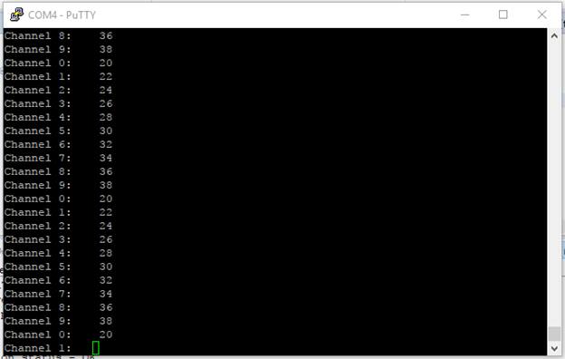
如上图所示,该程序将两组数据相加生成第三组数据,并通过UART发送这第三组数据。这是一个简单的演示程序,展示了如何在瑞萨消息框架下使用多消息源线程。
本指南为多消息源程序提供了基本框架。示例代码具有足够的通用性,可扩展用于不同应用场景。如果您觉得有用,欢迎复制并修改它。
问题 / 评论
如有任何问题或意见,请访问得捷电子技术论坛