介绍
意法半导体的STM32L053探索板搭载了STM32L0超低功耗系列中的STM32L053C8微控制器。该板载有电流测量模块,可由MCU读取以监控自身电流消耗。遗憾的是,由于缺乏相关文档说明,该功能在评估时较难使用。借助ST提供的示例代码,我们建立了与模块通信的基本流程,并开发出更简化的示例应用。结合STM32L0系列低功耗模式页面的信息,该应用可观察不同低功耗模式对MCU电流消耗的影响。
背景
ST提供三类开发板:Nucleo板、探索板和评估板。Nucleo板最为简单经济。除内置ST-LINK/V2调试器/编程器外,仅提供MCU的I/O接口扩展及少量按键和LED。评估板则价格昂贵,因其配备了评估对应MCU全部功能所需的完整硬件。探索板是折中之选。仅集成展示特定器件特性所需的必要组件。以下是STM32L053探索板(图1)的关键特性:
- STM32L053C8T6微控制器,64KB闪存,8KB RAM,LQFP48封装
- 板载ST-LINK/V2-1,带模式切换开关可独立作为ST-LINK/V2-2使用(配备SWD接口用于编程调试)
- 支持mbedTM平台(mbed.org)
- USB ST-LINK支持重枚举功能,提供三种接口:
- 虚拟串口
- 大容量存储
- 调试端口
- 板载供电:通过USB总线或外部5V电源
- 外部应用供电:3V和5V
- 一个线性触摸传感器或四个触摸按键
- IDD电流测量
- 2.04英寸电子墨水屏,172X72像素
- 四个LED指示灯:
- LD1(红/绿)用于USB通信
- LD2(红)表示3.3V电源开启
- 两个用户LED:SD3(绿),LD4(红)
- 两个按键(用户键和复位键)
- LQFP48 I/O扩展接口,便于快速连接原型板并轻松探测信号
- 丰富的免费软件资源,包含多种例程(STM32CubeL0软件包组成部分)
该开发板与同类Nucleo板的主要差异在于线性触摸传感器、IDD电流测量功能和电子墨水屏。这与板载主控MCU(STM32L053C8)的特性高度契合——这是一款具备触摸感应能力的超低功耗微控制器。后续章节将深入探讨IDD测量模块,以便有效评估STM32L0系列MCU的低功耗特性。

以下文档对STM32L053探索套件的应用开发极具参考价值:
电流消耗测量
STM32L053数据手册第6.1.8节指出,测量MCU电流消耗的推荐方案是高侧检测电路(图2)。即电流检测装置位于电源与负载(MCU)之间。STM32L053探索套件采用该方案实现其电流测量功能。简言之,用户既可使用自有电流测量仪器,也能通过板载电流测量模块来检测STM32L053C8的电流消耗。

开发板上的跳线JP4用于启用/禁用 IDD 测量功能。图3展示了JP4控制电流路径的示意图。若跳线连接1-2引脚(OFF位置),则VCC直连MCU,无法进行电流测量。若跳线帽连接引脚2和3(ON位置),电流将从VCC流经 IDD 测量模块,再流向MCU。在此配置下,MCU可与模块通信并请求获取瞬时电流消耗数据。
如需使用外部设备(如电流表)测量电流,应完全移除跳线帽。随后将仪器引线连接引脚1和2,以形成完整回路并保持高端检测方案。

IDD 测量模块
当JP4处于ON位置时,用户需了解如何读取电流测量值。Discovery开发板数据手册未提供相关信息(仅提及测量范围为50mA至100nA)。通过研究开发板原理图和示例代码,推导出简易操作流程。该模块可明确分为两部分:电流检测电阻网络和多功能扩展器(MFX)。电阻网络产生与电流速率成比例的电压信号,经放大后由MFX读取。MFX不仅将电压转换为电流测量值上报MCU,还作为电阻网络控制器,根据MCU电流消耗量自动配置最佳分流电阻值。
电流检测电阻
图4显示测量MCU电流消耗的电路。电路中有四个电流检测电阻(1Ω、24Ω、620Ω和10kΩ),已用紫色框标出。其中三个电阻与MOSFET串联,MOSFET栅极连接MFX的GPIO引脚。MFX通过控制这些MOSFET的通断组合来改变总分流电阻值。该设计确保分流电阻两端放大电压不超过3.3V,同时微小电流变化仍能产生显著电压变化。需注意第四个MOSFET连接MFX,用于校准目的。
图4中有四个运放用于放大分流电阻压降。标有U7B和U7D的两个运放作为电压跟随器,隔离电流检测电阻与差分放大器。U7C与特定电阻构成增益49.9的差分放大器。U7A作为另一个电压跟随器,为差分放大器提供0.14814V偏置电压。输出电压公式修正如下:
该偏移量可能是为了补偿MOSFET管上的压降。

多功能扩展器
MFX实质上是一个加载了固件的STM32L152芯片,使其能够充当触摸屏驱动、I/O扩展器和IDD控制器。在STM32L053 Discovery开发板上仅利用了最后一项功能,目的是将上述电流测量电路与主MCU(STM32L053C8)解耦。MCU可通过I2C总线(地址0x84)配置mfxstm32l152.h文件中定义的寄存器来控制MFX。该文件属于STM32CubeL0软件包,路径为en.stm32cubel0/STM32Cube_FW_L0_V1.6.0/Drivers/BSP/Components/mfxstm32l152。本节末尾提供的Excel文档"MFXSTM32L152_registers.xlsx"是MFX通用寄存器与IDD控制寄存器的映射表。
图5展示了MFX的电路原理图。注意图5与图4中相同的网络标签,这些标签揭示了MFX如何与电阻网络连接。但更重要的是黄色六边形框内的标签。这些是用于与开发板上其他芯片通信的双向端口。特别是MFX_I2C_SDA、MFX_I2C_SCL、MFX_IRQ_OUT和MFX_WAKEUP端口实现了MFX与MCU之间的通信。这些端口分别连接到STM32L053C8的PB9、PB8、PC13和PA1引脚。

由于缺乏MFX的官方文档,必须研究STM32L053 Discovery开发板的演示应用才能确定正确的初始化流程。该演示应用同样位于STM32CubeL0文件夹中,电流测量相关具体文件路径为en.stm32cubel0/STM32Cube_FW_L0_V1.6.0/Projects/STM32L053C8-Discovery/Demonstrations/Modules/iddmeasurement。基于这些文件,编写了清单1中的示例函数,展示如何初始化MFX以正确控制分流电阻并向MCU发送中断信号。基本流程概述如下:
- 首先对MFX执行软件复位,使其进入已知状态。随后立即插入100ms延时,确保MFX寄存器完成清零。
- 配置IRQ_OUT信号以通知MCU发生MFX事件。首先将MFX芯片上的物理引脚配置为推挽输出、高电平有效(即事件发生时MFX_IRQ_OUT引脚将从低电平跳变为高电平)。然后选择触发IRQ_OUT信号的事件类型。本示例中选择"IDD"和"ERROR"事件,即当IDD测量完成或MFX内部发生错误时,IRQ_OUT引脚将被置位。注意在
Idd_Init()函数开头,MCU上的PC13引脚被配置为在上升沿触发中断。 - MFX上启用了IDD测量功能。
- 当前测量参数已分配给MFX。这些参数包括电流检测电阻值和差分放大器的增益。同时还设定了触发复位前可施加到MFX的最小电压(VDD)。由于包含这些值的寄存器在内存中连续排列(地址0x82至0x8F),示例函数先将待写入值填充到数组,然后一次性将这14个值写入内存块。
代码清单 1 :初始化MFX进行IDD测量的示例
void Idd_Init( void )
{
    uint8_t params[14];

    /* Initialize GPIOs */
    // PC13: recieve MFX_IRQ_OUT signal
    RCC->IOPENR |= RCC_IOPENR_GPIOCEN; // enable clocks
    RCC->APB2ENR |= RCC_APB2ENR_SYSCFGEN; // ENABLE SYSTEM CONFIGURATION CONTROLLER CLOCK
    GPIOC->MODER &= ~( GPIO_MODER_MODE13 ); // Input mode
    // Configure external interrupt on MFX_IRQ_OUT (PC13)
    SYSCFG->EXTICR[3] |= SYSCFG_EXTICR4_EXTI13_PC; // PC13 is source for EXTI
    EXTI->IMR |= EXTI_IMR_IM13; // interrupt request from line 13 masked
    EXTI->RTSR |= EXTI_RTSR_TR13; // rising trigger enabled for input line 13

    // NOTE: I2C pins are configured in I2C_init function
    /* Initialize MFX */
    // reset MFX ( SYS_CTRL = SWRST )
    params[0] = 0x80;
    I2C_Write_Reg( I2C1, 0x84, 0x40, params, 1 );
    delay_ms( 100 );  // Give the registers time to be reset
    // IRQ pin -> push-pull, active high
    // ( IRQ_OUT = OUT_PIN_TYPE_PUSHPULL | OUT_PIN_POLARITY_HIGH )
    params[0] = 0x03;
    I2C_Write_Reg( I2C1, 0x84, 0x41, params, 1 );
    delay_ms( 1 );
    // IRQ source -> error and IDD ( IRQ_SRC_EN = IRQ_ERROR | IRQ_IDD )
    params[0] = 0x06;
    I2C_Write_Reg( I2C1, 0x84, 0x42, params, 1 );
    // Enable IDD function ( SYS_CTRL = IDD_EN )
    params[0] = 0x04;
    I2C_Write_Reg( I2C1, 0x84, 0x40, params, 1 );
    // Assign shunt values, gain value, and min VDD value
    params[0] = 0x03; params[1] = 0xE8;        // SH0 = 1000 mohm
    params[2] = 0x00; params[3] = 0x18;        // SH1 = 24 ohm
    params[4] = 0x02; params[5] = 0x6C;     // SH2 = 620 ohm
    params[6] = 0x00; params[7] = 0x00;        // SH3 = not included
    params[8] = 0x27; params[9] = 0x10;     // SH4 = 10,000 ohm
    params[10] = 0x13; params[11] = 0x7E; // Gain = 49.9 (4990)
    params[12] = 0x0B; params[13] = 0xB8;    // VDD_MIN = 3000 mV
    I2C_Write_Reg( I2C1, 0x84, 0x82, params, 14 );
    /* enable interrupts for external interrupt lines 4 - 15 */
    EXTI->PR |= EXTI_PR_PR13; // clear pending interrupt (if it is pending)
    NVIC_EnableIRQ( EXTI4_15_IRQn );
    NVIC_SetPriority( EXTI4_15_IRQn, IDD_INT_PRIO );
}
MFX初始化完成后,即可请求IDD测量。代码清单2展示了具体操作方法。第一步是指定预延迟时间(可选)。这是开始测量前需要等待的时间。设置IDD_PRE_DELAY寄存器的最高位将使预延迟值以20ms为单位,清除该位则切换为5ms单位。然后通过设置IDD_CTRL寄存器中的IDD_CTRL_REQ位和IDD_CTRL_SHUNT_NB位来请求测量(参见Excel文档)。由于Discovery板上有四个分流电阻,IDD_CTRL_SHUNT_NB字段写入0x04。
代码清单 2 :向MFX请求IDD 测量的示例
void Idd_req_meas( uint8_t predelay )
{
uint8_t param;
predelay |= 0x80; // IDD_PRE_DELAY |= IDD_PREDELAY_20_MS
I2C_Write_Reg( I2C1, 0x84, 0x81, &predelay, 1 ); //add predelay before Idd measurement
param = 0x09; // IDD_CTRL = ( ( 4 << 1 ) & IDD_CTRL_SHUNT_NB ) | IDD_CTRL_REQ
I2C_Write_Reg( I2C1, 0x84, 0x80, ¶m, 1 ); // request Idd measurement
}
测量完成后,可从三个IDD_VALUE寄存器读取数据,如代码清单3所示。但应首先读取IRQ_PENDING寄存器,检查IRQ_ERROR位是否被置位。若该位置位,尝试读取IDD测量值时MFX可能无响应。若无错误,可从内存地址0x14(IDD_VALUE_MSB)到0x16(IDD_VALUE_LSB)读取IDD值。随后必须通过设置IRQ_ACK寄存器中的IRQ_IDD位向MFX发送确认,告知中断已接收并处理。注意当IDD值的三个字节合并后,结果单位为10nA。若要转换为nA单位,只需乘以10。
代码清单 3 :从MFX读取IDD测量的示例
int Idd_get_meas( void )
{
    uint8_t temp[3];
    uint8_t ack;

    // check for errors
    I2C_Read_Reg( I2C1, 0x84, 0x08, temp, 1 );
    if ( temp[0] & 0x04 ) // if ( REG_IRQ_PENGDING & IRQ_ERROR )
    {
        Idd_Init();
        CURR_MEAS_POS();  // move cursor to current measurement position
        USART_puts( USART1, "MFX ERROR" );
        return -1;
    }

    I2C_Read_Reg( I2C1, 0x84, 0x14, temp, 3 ); // read current measurement
    ack = 0x02;
    I2C_Write_Reg( I2C1, 0x84, 0x44, &ack, 1 ); // acknowledge Idd from MFX
    return (temp[0]<<16) + (temp[1]<<8) + temp[2];
}
寄存器映射表
如前所述,下方附有记录相关寄存器的Excel表格文档。mfxstm32l152.h文件中的定义经过整理,用于填充地址和位字段列。同样,任何有用的注释都被放置在注释和权限列中。复位值列是通过运行一个测试确定的,该测试在软件复位后立即读取每个寄存器。存在许多空白单元格,因为某些寄存器注释不够完善(或完全没有注释),且部分位字段未定义。尽管如此,这份电子表格对于希望理解上述示例函数中看似随机的十六进制数字实际含义的人来说,仍是一个有用的参考。
- MFXSTM32L152_registers.zip (13.5 KB)
示例应用
STM32L053 Discovery套件预装的演示程序允许用户通过触摸传感器选择四种操作模式,同时功耗数据会显示在电子纸屏幕上。这些模式包括运行模式、睡眠模式、低功耗睡眠模式和停止模式。为了进一步凸显STM32L053器件的低功耗特性,同时避免ST硬件抽象库的复杂性,我们编写了一个使用更少外设和板载功能的新应用。这个新示例应用包含演示程序中未涵盖的两种低功耗模式(低功耗运行模式和待机模式),并以每秒约一次的频率持续进行测量。
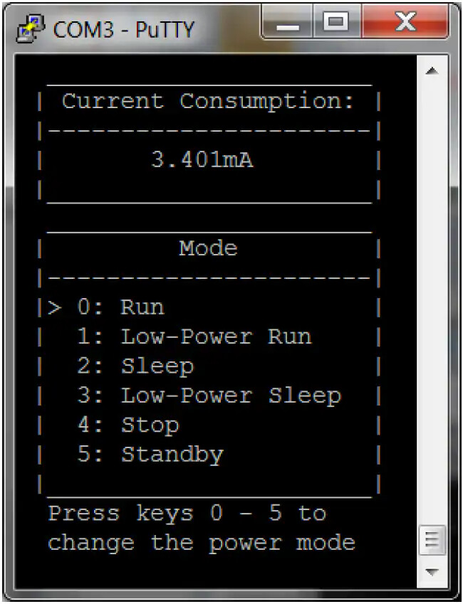
终端模拟器为该应用提供用户界面。图6是输出结果的屏幕截图。顶部窗口显示当前测量值,底部窗口列出操作模式。箭头指向当前模式,最底部显示选择不同模式的说明。任何终端模拟器程序(如PuTTY、Tera Term、CoolTerm等)均可使用,只需将波特率设置为4800,并确保每次换行(LF)都隐式包含回车(CR)。若STM32L053 Discovery板背面标签为"MB1143 B-01"或更新版本,需短接SB2和SB3焊桥以使USART与虚拟COM端口通信(参见Discovery板用户手册第4.14节)。
该应用的核心是有限状态机(FSM),每个状态对应六种操作模式之一。每个状态的进入动作是配置系统时钟、电源控制寄存器和M0+内核寄存器的函数,以便将设备置于所需操作模式。这些函数均命名为enter_<Mode>(),其中<Mode>可替换为:Run、LPRun、Sleep、LPSleep、Stop或Standby。有关这些函数及其对应低功耗模式的更多信息,请参阅STM32L0系列低功耗模式页面。
除FSM外,还有一个后台线程处理电流测量功能。当MFX拉高IRQ_OUT线表示电流测量就绪时(记得MCU的PC13用于触发外部中断),该线程就会执行。该线程使用前一节讨论的流程获取电流测量值、显示数据并请求新测量。为验证IDD测量模块当前测量结果的准确性,采用数字万用表进行对比测试。每种模式均采用两种方法各测量三次,平均值记录于表1中。为确保万用表测量稳定性,未初始化MFX模块。此举避免后台线程运行导致MCU每秒临时进入运行模式。数据显示,对于运行模式、睡眠模式和低功耗睡眠模式,IDD模块虽非最精确方案,但考虑到电路简洁性,其测量精度已相当可观。
表 1 : MCU 在不同工作模式下的电流消耗测量对比
| 模式 | IDD 模块 | 万用表 |
|---|---|---|
| 运行 | 3.399毫安 | 3.451毫安 |
| 低功耗运行 | 44.052微安 | 44.063微安 |
| 睡眠 | 1.331毫安 | 1.474毫安 |
| 低功耗睡眠 | 14.179微安 | 15.233微安 |
| 停止 | 451纳安 | 443纳安 |
| 待机 | 297纳安 | 288 纳安 |
完整示例代码
由于这是一个相对简单的应用程序,未使用ST的硬件抽象库,所有代码均置于main.c文件中(如下方清单4所示)。代码使用Keil的µVision5 IDE编写,包含大量注释,并(希望)以非常符合逻辑的方式组织。对于Keil开发工具的新手,下面概述了从头创建此应用程序的步骤。
- 打开µVision5,进入项目(Project) > 管理(Manage) > 包安装程序(Pack Installer)…
- 在左侧窗口中选择设备(STMicroelectronics > STM32L0 Series > STM32L053 > STM32L053C8 > STM32L053C8Tx)
- 在右侧窗口中,点击"Keil::STM32L0xx_DFP"和"ARM::CMSIS"旁边的安装按钮
- 关闭包安装程序窗口,进入项目(Project) > 新建µVision项目(New µVision Project)…
- 导航至项目存放文件夹,输入项目名称(如STM32L035-DISCO_current_meas),点击保存(Save)
- 选择设备(在左下角框中导航至STMicroelectronics > STM32L0 Series > STM32L053 > STM32L053C8 > STM32L053C8Tx)并点击确定(OK)
- 展开"CMSIS"软件组件,勾选"Core"对应的复选框
- 从"Device"软件组件对应的下拉菜单中选择"Standalone"。展开"Device"软件组件,勾选"Startup"对应的复选框。点击确定(OK)
- 在项目菜单中展开"Target 1",右键点击"Source Group 1",选择添加现有文件到组’Source Group 1’…
- 导航至main.c存储位置,选择该文件,点击添加(Add),然后点击关闭(Close)
- 进入项目(Project) > 目标’Target 1’的选项…(注意:可能需要先打开并关闭组’Source Group 1’的选项才能使此选项出现)
- 在调试选项卡下,从右上角下拉菜单中选择ST-Link调试器
- 点击该下拉菜单旁边的设置(Settings),进入Flash下载(Flash Download)选项卡,点击唯一的编程算法选项(STM32L0 64KB Flash),然后点击确定(OK)
- 再次点击确定(OK),进入项目(Project) > 构建目标(Build Target)
- 最后进入Flash > 下载(Download)(下载完成后可能需要按下复位按钮才能使用应用程序)
如果一切顺利,开发板应已完成编程并准备就绪。只需打开终端模拟器,将波特率设置为4800,并打开正确的COM端口。请注意,某些终端模拟器在接收到换行符时不会自动打印回车符,因此必要时需更改该设置。
代码清单 4 :main.c
/*******************************************************************************
*
* Program: Current Meas. (rev2)
*
* Author: Matt Mielke
*
* Company: Digi-Key Electronics
*
* Date: September 21, 2016
*
* Description: This program provides an example of interfacing with the MFX
* in order to provide current measurements for each sleep mode
* offered by the STM32L053C8.
*
* Modifications:
* Date Comment
*---------- ------------------------------------------------------------------
*
*
*******************************************************************************/
/******************************************************************************/
/* Includes */
/******************************************************************************/
#include "stm32l0xx.h"
#include <stdio.h>
/******************************************************************************/
/* Defines */
/******************************************************************************/
// System clocks
#define SYSCLK_FREQ ( SystemCoreClock )
#define AHB_PRESC 1
#define HCLK_FREQ ( SYSCLK_FREQ / AHB_PRESC )
#define APB1_PRESC 1
#define PCLK1_FREQ ( HCLK_FREQ / APB1_PRESC )
#define APB2_PRESC 1
#define PCLK2_FREQ ( HCLK_FREQ / APB2_PRESC )
#define USART1CLK_FREQ PCLK2_FREQ
#define I2C1CLK_FREQ PCLK1_FREQ
// USART
#define U1_BAUD_RATE 4800
#define TERM_USART USART1 // USART periph. that interfaces with terminal
// Finite State Machine (FSM)
#define NUM_STATES 6
#define RUN &fsm[0]
#define LPRUN &fsm[1]
#define SLEEP &fsm[2]
#define LPSLEEP &fsm[3]
#define STOP &fsm[4]
#define STANDBY &fsm[5]
// Interrupts
#define IDD_INT_PRIO 3
#define BTN_INT_PRIO 3
#define USART_INT_PRIO 0
// ANSI Escape Sequences
#define CLEAR_TERMINAL() USART_puts( TERM_USART, "\x1B" "[2J" )
#define CURSOR_HOME() USART_puts( TERM_USART, "\x1B" "[H" )
#define CURSOR_OFF() USART_puts( TERM_USART, "\x1B" "[?25l" )
#define CURSOR_BACK() USART_puts( TERM_USART, "\x1B" "[1D" )
#define SAVE_CURSOR_POS() USART_puts( TERM_USART, "\x1B" "7" )
#define RESTORE_CURSOR_POS() USART_puts( TERM_USART, "\x1B" "8" )
// Application Specific Escape Sequences
#define CURR_MEAS_POS() USART_puts( TERM_USART, "\x1B" "[4;10H" )
#define DEBUG_POS() USART_puts( TERM_USART, "\x1b" "[4;30H" )
#define MESSASAGE_POS() USART_puts( TERM_USART, "\x1B" "[16;3H" )
#define PRINT_UI() USART_puts( TERM_USART, \
" ______________________ \n" \
" | Current Consumption: |\n" \
" |----------------------|\n" \
" | |\n" \
" |______________________|\n" \
" ______________________ \n" \
" | Mode |\n" \
" |----------------------|\n" \
" | 0: Run |\n" \
" | 1: Low-Power Run |\n" \
" | 2: Sleep |\n" \
" | 3: Low-Power Sleep |\n" \
" | 4: Stop |\n" \
" | 5: Standby |\n" \
" |______________________|\n" )
/******************************************************************************/
/* Structures and Enumerations */
/******************************************************************************/
// Each state contains an entry action and an array of pointers to the next
// state corresponding to each possible input.
typedef const struct State
{
void (*entry_action)( void );
const struct State* next[NUM_STATES];
}State_Type;
/******************************************************************************/
/* Function Prototypes */
/******************************************************************************/
void Config_SysClk_HSI16( void );
void Config_SysClk_MSI_131( void );
void delay_ms( int t_ms );
void enter_Run( void );
void enter_LPRun( void );
void enter_Sleep( void );
void enter_LPSleep( void );
void enter_Stop( void );
void enter_Standby( void );
void I2C1_Init( void );
void I2C_Read_Reg( I2C_TypeDef* pI2C, uint16_t dev_addr, uint8_t reg, uint8_t* data, uint8_t count );
void I2C_Write_Reg( I2C_TypeDef* pI2C, uint16_t dev_addr, uint8_t reg, uint8_t* data, uint8_t count );
void Idd_Init( void );
int Idd_get_meas( void );
void Idd_report_meas( int meas );
void Idd_req_meas( uint8_t predelay );
void Idd_RestoreContext(void);
void Idd_SaveContext(void);
void SysTick_Init( double overflow_period );
void USART1_Init( void );
char USART_getc( USART_TypeDef* pUSART );
void USART_putc( USART_TypeDef* pUSART, char character );
void USART_puts( USART_TypeDef* pUSART, char* str );
/******************************************************************************/
/* Global Variables */
/******************************************************************************/
uint8_t user_input = 0; // input to FSM
// the context of the gpio modes are saves in these variables
uint32_t GPIOA_MODER = 0, GPIOB_MODER = 0, GPIOC_MODER = 0;
State_Type fsm[NUM_STATES] = // the FSM
{// entry_action //next state
{ enter_Run, { NULL, LPRUN, SLEEP, LPSLEEP, STOP, STANDBY } },
{ enter_LPRun, { RUN, NULL, RUN, LPSLEEP, RUN, RUN } },
{ enter_Sleep, { RUN, LPRUN, SLEEP, LPSLEEP, STOP, RUN } },
{ enter_LPSleep, { RUN, LPRUN, RUN, LPSLEEP, RUN, RUN } },
{ enter_Stop, { RUN, LPRUN, SLEEP, LPSLEEP, STOP, STANDBY } },
{ enter_Standby, { RUN, LPRUN, SLEEP, LPSLEEP, STOP, STANDBY } },
};
State_Type* curr_state = RUN; // store current state of program
// ANSI escape sequences
const char ModePosition[6][8] = { // position of '>' for each mode
{ "\x1B" "[9;3H" },
{ "\x1B" "[10;3H" },
{ "\x1B" "[11;3H" },
{ "\x1B" "[12;3H" },
{ "\x1B" "[13;3H" },
{ "\x1B" "[14;3H" }, };
/******************************************************************************/
/* Interrupt Service Routines */
/******************************************************************************/
/* Entered if data is recieved from USART1 */
void USART1_IRQHandler( void )
{
if ( USART1->ISR & USART_ISR_RXNE ) // Data was received
{
// NOTE: flag cleared by reading USART1->RDR
user_input = ( USART_getc( USART1 ) & 0xF );
if ( user_input >= NUM_STATES )
{
user_input = NUM_STATES - 1;
}
SCB->SCR &= ~( SCB_SCR_SLEEPONEXIT_Msk ); // go to FSM control loop
}
}
/* Entered if user button is pressed in Stop mode (and only Stop mode) */
void EXTI0_1_IRQHandler( void )
{
if ( EXTI->PR & EXTI_PR_PR0 ) // User button pressed
{
EXTI->PR |= EXTI_PR_PR0; // Acknowledge interrupt
user_input = 0; // enter the RUN state
// disable this external interrupt
EXTI->IMR &= ~( EXTI_IMR_IM0 );
NVIC_DisableIRQ( EXTI0_1_IRQn );
}
}
/* Entered when Idd measurement is ready */
// not recognized by the FSM (it is a background thread)
// (must be entered by software when waking from Standby mode)
void EXTI4_15_IRQHandler( void )
{
if ( EXTI->PR & EXTI_PR_PR13 ) // Idd measurement ready
{
EXTI->PR |= EXTI_PR_PR13; // Acknowledge interrupt
Idd_report_meas( Idd_get_meas() );
Idd_req_meas( 50 ); // 1 second
// ensure USART transmission completes before stopping the peripheral
while ( !( USART1->ISR & USART_ISR_TC ) );
}
}
/*******************************************************************************
* Function: main
* Author: Matt Mielke
* Desctription: This is entry point for the program. As always, SystemInit()
* is called to ensure the system is in a known state. The
* enter_Run funciton will initialize the system frequency and the
* peripherals dependent on that frequency. Then, Idd_Init() will
* initialize the MFX to take current measurements and interrupt
* execution when the measurement is ready.
* Since Standby mode is used in this application (and it
* essentially resets the device) the SBF flag must be checked once
* the system is up and running. If the device was woken up from
* Standby mode, the state of the user button must be checked to
* determine what triggered the wake-up event. If the user button
* is depressed, the user woke the device wanting to re-enter Run
* mode. The the user button is not depressed, the MFX woke the
* device wanting to report a current measurement.
* If the program is executing for the first time, the terminal
* is cleared and the GUI is redrawn. In order to avoid having to
* store the previous state, the terminal can save the last
* position of the '>' character so it can be returned to, cleared,
* and redrawn in the current position. The user interface is
* updated each time the FSM control loop is entered.
* Other than update the user interface, the FSM control loop
* simply uses the user input to change the state of the program.
* These state transistions are defined by the fsm structure above.
* Date: 09-21-16
*******************************************************************************/
int main(void)
{
SystemInit();
enter_Run(); // start program in the running state
/* If we woke up from Standby mode, restore FSM */
if ( PWR->CSR & PWR_CSR_SBF ) // Did we wakeup from standby mode?
{
PWR->CR |= PWR_CR_CSBF; // clear the Standby flag
RCC->IOPENR |= RCC_IOPENR_GPIOAEN; // port A clock enabled
GPIOA->MODER &= ~( GPIO_MODER_MODE0 ); // PA0 in input mode
if ( GPIOA->IDR & GPIO_IDR_ID0 ) // if user button (PA0) is being pressed
{
curr_state = STANDBY;
PWR->CSR &= ~( PWR_CSR_EWUP1 | PWR_CSR_EWUP2 ); // disable wake-up pins
Idd_Init();
Idd_req_meas( 50 ); // request initial measurement (1 second)
}
else // MFX caused wake up, so print current meas. and re-enter Standy mode
{
/* Enable external interrupt 13 */
EXTI->IMR |= EXTI_IMR_IM13; // interrupt request from line 13 masked
EXTI->PR |= EXTI_PR_PR13; // clear pending interrupt (if it is pending)
NVIC_EnableIRQ( EXTI4_15_IRQn );
user_input = 5;
EXTI->SWIER |= EXTI_SWIER_SWI13; // trigger Idd meas. ready interrupt
}
}
/* If this is the first execution, initialize FSM */
else
{
CURSOR_OFF();
CLEAR_TERMINAL();
CURSOR_HOME();
PRINT_UI();
USART_puts( USART1, (char*)ModePosition[user_input] );
USART_putc( USART1, '>' );
SAVE_CURSOR_POS();
MESSASAGE_POS();
USART_puts( USART1, "Press keys 0 - 5 to \n change the power mode " );
Idd_Init();
Idd_req_meas( 50 ); // request initial measurement (1 second)
}
// FSM and GUI control loop
while( 1 )
{
if ( curr_state->next[user_input] != NULL )
{
__disable_irq(); // no interrupts may use the USART right now...
// update position of arrow ('>')
RESTORE_CURSOR_POS();
CURSOR_BACK(); // move cursor back one space
USART_putc( USART1, ' ' ); // overwrite '>'
USART_puts( USART1, (char*)ModePosition[user_input] );
USART_putc( USART1, '>' );
SAVE_CURSOR_POS();
// update state
curr_state = curr_state->next[user_input];
// update instructions for changing state
MESSASAGE_POS(); // move cursor to message position
if ( curr_state == STOP )
{
USART_puts( USART1, "Press the user button \n to enter run mode " );
}
else if ( curr_state == STANDBY )
{
USART_puts( USART1, "Press and hold the user\n button to enter run mode" );
}
else
{
USART_puts( USART1, "Press keys 0 - 5 to \n change the power mode " );
}
// wait for USART transmission to complete
while ( !( USART1->ISR & USART_ISR_TC ) );
__enable_irq(); // ...interrupts may use the USART again
// perform entry action of the new state
curr_state->entry_action();
}
}
return 0; // we should never get here
}
/*******************************************************************************
* Function: Config_SysClk_HSI16
* Author: Matt Mielke
* Desctription: This function will configure the system clock to run at 16 MHz
* using the High Speed Internal 16 MHz oscillator. All other
* oscillators are disabled and the SystemCoreClock global variable
* is update using the SystemCoreClockUpdate() function.
* Date: 09-22-16
*******************************************************************************/
void Config_SysClk_HSI16( void )
{
/* Enable Clock */
RCC->CR |= RCC_CR_HSION; // HSI16 oscillator ON
while ( !( RCC->CR & RCC_CR_HSIRDY ) ); // wait until HSI16 is ready
/* Switch System Clock */
// HSI16 oscillator used as system clock
RCC->CFGR = ( RCC->CFGR & ~RCC_CFGR_SW ) | RCC_CFGR_SW_HSI;
while ( ( RCC->CFGR & RCC_CFGR_SWS ) != RCC_CFGR_SWS_HSI ); // wait until switched
/* Disable other clocks (excluding LSE and LSI) */
RCC->CR &= ~( RCC_CR_MSION | RCC_CR_HSEON | RCC_CR_PLLON );
SystemCoreClockUpdate();
}
/*******************************************************************************
* Function: Config_SysClk_MSI_131
* Author: Matt Mielke
* Desctription: This function will configure the system clock to run at
* 131,072 Hz using the Multi-Speed Internal oscillator. All other
* oscillators are disabled and the SystemCoreClock global variable
* is update using the SystemCoreClockUpdate() function.
* Date: 09-22-16
*******************************************************************************/
void Config_SysClk_MSI_131( void )
{
/* Enable and Configure Clock */
RCC->CR |= RCC_CR_MSION;
RCC->ICSCR = ( RCC->ICSCR & ~RCC_ICSCR_MSIRANGE ) | RCC_ICSCR_MSIRANGE_1;
while ( !( RCC->CR & RCC_CR_MSIRDY ) ); // wait until MSI is ready
/* Switch System Clock */
// MSI oscillator used as system clock
RCC->CFGR = ( RCC->CFGR & ~RCC_CFGR_SW ) | RCC_CFGR_SW_MSI;
while ( ( RCC->CFGR & RCC_CFGR_SWS ) != RCC_CFGR_SWS_MSI ); // wait unit switched
/* Disable other clocks (excluding LSE and LSI) */
RCC->CR &= ~( RCC_CR_HSION | RCC_CR_HSEON | RCC_CR_PLLON );
SystemCoreClockUpdate();
}
/*******************************************************************************
* Function: delay_ms
* Author: Matt Mielke
* Desctription: This function assumes the SysTick peripheral is configured to
* underflow every ms. It simply does nothing for t_ms underflows
* in order to delay t_ms milliseconds.
* Date: 09-12-16
*******************************************************************************/
void delay_ms( int t_ms )
{
SysTick->VAL = 0;
while ( t_ms > 0 )
{
while ( !( SysTick->CTRL & SysTick_CTRL_COUNTFLAG_Msk ) ); // wait for underflow
t_ms--;
}
}
/*******************************************************************************
* Function: enter_Run
* Author: Matt Mielke
* Desctription: This function configures the device for run mode. To avoid
* problems entering the low-power modes, the regulator
* configuration is reset right away. Then, the system frequency
* is set to 16MHz and the peripherals dependent on it are
* initialized.
* Date: 09-21-16
*******************************************************************************/
void enter_Run( void )
{
/* Enable Clocks */
RCC->APB1ENR |= RCC_APB1ENR_PWREN;
/* Force the regulator into main mode */
// Reset LPRUN bit
PWR->CR &= ~( PWR_CR_LPRUN );
// LPSDSR can be reset only when LPRUN bit = 0;
PWR->CR &= ~( PWR_CR_LPSDSR );
/* Set HSI16 oscillator as system clock */
Config_SysClk_HSI16();
// Reinitialize peripherals dependent on clock speed
USART1_Init();
SysTick_Init( 0.001 );
I2C1_Init();
}
/*******************************************************************************
* Function: enter_LPRun
* Author: Matt Mielke
* Desctription: This function will configure the system for Low-power run
* mode and enter is using the procedure outlined on page __ of
* reference manual. After enabling/disabling the desired clocks,
* the system frequency is set to 131 kHz. It could be lower than
* this, but serial communication would become more difficult (or
* even impossible). The frequency dependent peripherals are then
* re-initialized and the regulator is forced into low-power mode.
* Date: 09-21-16
*******************************************************************************/
void enter_LPRun( void )
{
/* 1. Each digital IP clock must be enabled or disabled by using the
RCC_APBxENR and RCC_AHBENR registers */
RCC->APB1ENR |= RCC_APB1ENR_PWREN;
/* 2. The frequency of the system clock must be decreased to not exceed the
frequency of f_MSI range1. */
Config_SysClk_MSI_131();
// Reinitialize peripherals dependent on clock speed
USART1_Init();
SysTick_Init( 0.001 );
I2C1_Init();
/* 3. The regulator is forced in low-power mode by software
(LPRUN and LPSDSR bits set ) */
PWR->CR &= ~PWR_CR_LPRUN; // Be sure LPRUN is cleared!
PWR->CR |= PWR_CR_LPSDSR; // must be set before LPRUN
PWR->CR |= PWR_CR_LPRUN; // enter low power run mode
}
/*******************************************************************************
* Function: enter_Sleep
* Author: Matt Mielke
* Desctription: This function will enter Sleep mode by properly configuring
* the SLEEPDEEP bit in the SCR. The SLEEPONEXIT bit is also set as
* the device will only need to be awake to service interrups.
* Also, the Flash is not disabled in order to minimize wake-up
* latency. Sleep mode is entered with the WFI instruction.
* Date: 09-22-16
*******************************************************************************/
void enter_Sleep( void )
{
/* Configure low-power mode */
SCB->SCR &= ~( SCB_SCR_SLEEPDEEP_Msk ); // low-power mode = sleep mode
SCB->SCR |= SCB_SCR_SLEEPONEXIT_Msk; // reenter low-power mode after ISR
/* Ensure Flash memory stays on */
FLASH->ACR &= ~FLASH_ACR_SLEEP_PD;
__WFI(); // enter low-power mode
}
/*******************************************************************************
* Function: enter_LPSleep
* Author: Matt Mielke
* Desctription: This function will put the device in Low-power sleep mode
* by following the procedure described on page __ of the
* reference manual. Power consumption is minimized by disabling
* the Flash and in order to get the regulator into low-power mode,
* the system frequency is decreased to 131 kHz. The necessary
* peripherals are re-initialized and Low-power sleep mode is
* entered through the WFI instuction.
* Date: 09-22-16
*******************************************************************************/
void enter_LPSleep( void )
{
/* 1. The Flash memory can be switched off by using the control bits
(SLEEP_PD in the FLASH_ACR register). This reduces power consumption
but increases the wake-up time. */
FLASH->ACR |= FLASH_ACR_SLEEP_PD;
/* 2. Each digital IP clock must be enabled or disabled by using the
RCC_APBxENR and RCC_AHBENR registers */
RCC->APB1ENR |= RCC_APB1ENR_PWREN;
/* 3. The frequency of the system clock must be decreased to not exceed the
frequency of f_MSI range1. */
// Set MSI 131.072 kHz as system clock
Config_SysClk_MSI_131();
// Reinitialize peripherals dependent on clock speed
USART1_Init();
SysTick_Init( 0.001 );
I2C1_Init();
/* 4. The regulator is forced in low-power mode by software
(LPSDSR bits set ) */
PWR->CR |= PWR_CR_LPSDSR; // voltage regulator in low-power mode during sleep
/* 5. Follow the steps described in Section 6.3.5: Entering low-power mode */
SCB->SCR &= ~( SCB_SCR_SLEEPDEEP_Msk ); // low-power mode = sleep mode
SCB->SCR |= SCB_SCR_SLEEPONEXIT_Msk; // reenter low-power mode after ISR
__WFI(); // enter low-power mode
}
/*******************************************************************************
* Function: enter_Stop
* Author: Matt Mielke
* Desctription: This function will not only configure and enter Stop mode,
* but also configure an external interrupt connected to PA0 (the
* user button) in order to wake the device. In order to use less
* power, V_{REFINT} is disabled, the regulator is placed in
* low-power mode, and the I/O pins are placed in analog mode. Stop
* mode is entered using the WFI instruction and once the device is
* woken, the system is restored to a working state before the
* external interrupt ISR is entered.
* Date: 09-23-16
*******************************************************************************/
void enter_Stop( void )
{
/* Enable Clocks */
RCC->APB1ENR |= RCC_APB1ENR_PWREN;
RCC->IOPENR |= RCC_IOPENR_GPIOAEN;
/* Configure PA0 as External Interrupt */
GPIOA->MODER &= ~( GPIO_MODER_MODE0 ); // PA0 is in Input mode
EXTI->IMR |= EXTI_IMR_IM0; // interrupt request from line 0 not masked
EXTI->RTSR |= EXTI_RTSR_TR0; // rising trigger enabled for input line 0
// Enable interrupt in the NVIC
NVIC_EnableIRQ( EXTI0_1_IRQn );
NVIC_SetPriority( EXTI0_1_IRQn, BTN_INT_PRIO );
/* Prepare to enter stop mode */
PWR->CR |= PWR_CR_CWUF; // clear the WUF flag after 2 clock cycles
PWR->CR &= ~( PWR_CR_PDDS ); // Enter stop mode when the CPU enters deepsleep
// V_REFINT startup time ignored | V_REFINT off in LP mode | regulator in LP mode
PWR->CR |= PWR_CR_FWU | PWR_CR_ULP | PWR_CR_LPSDSR;
RCC->CFGR |= RCC_CFGR_STOPWUCK; // HSI16 oscillator is wake-up from stop clock
SCB->SCR |= SCB_SCR_SLEEPDEEP_Msk; // low-power mode = stop mode
__disable_irq();
Idd_SaveContext();
I2C1->CR1 &= ~I2C_CR1_PE; // Address issue 2.5.1 in Errata
__WFI(); // enter low-power mode
I2C1->CR1 |= I2C_CR1_PE;
Idd_RestoreContext();
__enable_irq(); // <-- go to isr
}
/*******************************************************************************
* Function: enter_Standby
* Author: Matt Mielke
* Desctription: This function will enter Standby mode and enable the devices
* two wake-up pins (PA0 and PC13). This way, either the user
* button or a signal from the MFX can wake the device.
* Date: 09-27-16
*******************************************************************************/
void enter_Standby( void )
{
/* Enable Clocks */
RCC->APB1ENR |= RCC_APB1ENR_PWREN;
/* Prepare for Standby */
// if WKUP pins are already high, the WUF bit will be set
PWR->CSR |= PWR_CSR_EWUP1 | PWR_CSR_EWUP2;
PWR->CR |= PWR_CR_CWUF; // clear the WUF flag after 2 clock cycles
PWR->CR |= PWR_CR_ULP; // V{REFINT} is off in low-power mode
PWR->CR |= PWR_CR_PDDS; // Enter Standby mode when the CPU enters deepsleep
SCB->SCR |= SCB_SCR_SLEEPDEEP_Msk; // low-power mode = stop mode
__WFI(); // enter low-power mode
}
/*******************************************************************************
* Function: I2C1_Init
* Author: Matt Mielke
* Desctription: Pins PB8 and PB9 are configured as the I2C1_SCL and I2C_SDA
* pins, respectively. The timing register of the I2C1 peripheral
* is configured to work across a frequency range of 131072 Hz to
* 32 MHz. This is accomplished by setting the SCLH and SCLL
* bitfields to 5 (as this provides a minumum f_{SCL} of about
* 10 kHz, and setting the SCLDEL and SDADEL bitfields to 0. Note
* that the value of SDADEL is of little concern because
* NOSTRETCH = 0. The value of PRESC is dynamically chosen based
* on the frequency of the I2C1 clock. No interrups are enabled as
* the MFX will alert the device when measurements are ready.
* Date: 09-13-16
*******************************************************************************/
void I2C1_Init( void )
{
int presc; // prescaler
/* Enable Clocks */
RCC->APB1ENR |= RCC_APB1ENR_I2C1EN; // Enable I2C1 clock
RCC->IOPENR |= RCC_IOPENR_GPIOBEN; // Enable GPIOB clock
/* Configure GPIOs */
// PB8 = MFX_I2C_SCL -> alternate function mode
// PB9 = MFX_I2C_SDA -> alternate function mode
GPIOB->MODER &= ~( GPIO_MODER_MODE8 | GPIO_MODER_MODE9 );
GPIOB->MODER |= GPIO_MODER_MODE8_1 | GPIO_MODER_MODE9_1;
// AFSEL8 = 4 -> I2C1_SCL // AFSEL9 = 4 -> I2C1_SDA
GPIOB->AFR[1] |= (4 << 0) | (4 << 4);
GPIOB->OTYPER |= GPIO_OTYPER_OT_8 | GPIO_OTYPER_OT_9; // output open drain
/* Configure I2C1 */
I2C1->CR1 &= ~( I2C_CR1_PE ); // ensure I2C1 is disabled
// Try to configure f_SCL = ~150 kHz
// NOTE: NOSTRETCH must equal 0 (default)
// t_{PRESC} = (PRESC+1) x t_{I2CCLK} -> PRESC = f_{I2CCLK}/f_{PRESC} - 1
presc = I2C1CLK_FREQ / 150000 - 1;
presc = presc < 0 ? 0 : presc; // clip presc to 0 if negative
presc = presc > 15 ? 15 : presc; // clip presc to 15 if larger
I2C1->TIMINGR = 0; // clear TIMINGR
// SCLDEL = 0 // SDADEL = 0 // SCLH = 5 // SCLL = 5 // PRESC = presc
I2C1->TIMINGR |= ( (5<<8) & I2C_TIMINGR_SCLH ) | ( 5 & I2C_TIMINGR_SCLL ) |
( ( presc << 28 ) & I2C_TIMINGR_PRESC );
/* Enable I2C1 */
I2C1->CR1 |= I2C_CR1_PE;
}
/*******************************************************************************
* Function: I2C_Read_Reg
* Author: Matt Mielke
* Desctription: This function will read the contents of the slave's memory
* starting at the specified address. The user must specify which
* I2C peripheral to use, the slave address, the address of the
* register to start from, and the number of bytes to be read.
* Also, a buffer for the data to be stored in must be provided.
* Date: 09-13-16
*******************************************************************************/
void I2C_Read_Reg( I2C_TypeDef* pI2C, uint16_t dev_addr, uint8_t reg, uint8_t* data, uint8_t count )
{
uint32_t temp_CR2;
// begin transaction by sending the register address
temp_CR2 = pI2C->CR2;
temp_CR2 &= ~( I2C_CR2_RELOAD | I2C_CR2_NBYTES | I2C_CR2_RD_WRN | I2C_CR2_SADD | I2C_CR2_AUTOEND );
temp_CR2 |= ( dev_addr & I2C_CR2_SADD ) | ( ( 1 << 16 ) & I2C_CR2_NBYTES )
| I2C_CR2_START;
pI2C->CR2 = temp_CR2;
while ( !( pI2C->ISR & I2C_ISR_TXIS ) ); // wait for TXDR to be empty
pI2C->TXDR = reg; // send register address
while ( !( pI2C->ISR & I2C_ISR_TC ) ); // wait for transfer to complete
// continue transaction by reading from slave
temp_CR2 = pI2C->CR2;
temp_CR2 &= ~( I2C_CR2_RELOAD | I2C_CR2_NBYTES | I2C_CR2_SADD );
temp_CR2 |= ( dev_addr & I2C_CR2_SADD ) | ( ( count << 16 ) & I2C_CR2_NBYTES )
| I2C_CR2_RD_WRN | I2C_CR2_AUTOEND | I2C_CR2_START;
pI2C->CR2 = temp_CR2;
do
{
while ( !( pI2C->ISR & I2C_ISR_RXNE ) ); // wait for data to be received
*data = pI2C->RXDR;
data++;
count--;
} while ( count > 0 );
while ( !( pI2C->ISR & I2C_ISR_STOPF ) ); // wait for stop to be detected
pI2C->ICR |= I2C_ICR_STOPCF; // clear the stop detection flag
}
/*******************************************************************************
* Function: I2C_Write_Reg
* Author: Matt Mielke
* Desctription: This function will write to the slave's memory starting at the
* provided starting address. Besides this, the I2C peripheral to
* be used, the slave address, the number of bytes to write,
* and a buffer containing the data to be written must be provided.
* Date: 09-13-16
*******************************************************************************/
void I2C_Write_Reg( I2C_TypeDef* pI2C, uint16_t dev_addr, uint8_t reg, uint8_t* data, uint8_t count )
{
uint32_t temp_CR2;
// begin transaction
temp_CR2 = pI2C->CR2;
temp_CR2 &= ~( I2C_CR2_RELOAD | I2C_CR2_NBYTES | I2C_CR2_RD_WRN | I2C_CR2_SADD );
temp_CR2 |= ( dev_addr & I2C_CR2_SADD ) | ( ( ( count + 1 ) << 16 ) & I2C_CR2_NBYTES )
| I2C_CR2_AUTOEND | I2C_CR2_START;
pI2C->CR2 = temp_CR2;
while ( !( pI2C->ISR & I2C_ISR_TXIS ) ); // wait for TXDR to be empty
pI2C->TXDR = reg; // send register address
// send data
do
{
while ( !( pI2C->ISR & I2C_ISR_TXIS ) ); // wait for TXDR to be empty
pI2C->TXDR = *data;
data++;
count--;
} while ( count > 0 );
while ( !( pI2C->ISR & I2C_ISR_TXE) ); // TXDR is empty and all data has been sent
while ( !( pI2C->ISR & I2C_ISR_STOPF ) ); // wait for stop to be detected
pI2C->ICR |= I2C_ICR_STOPCF; // clear the stop detection flag
}
/*******************************************************************************
* Function: Idd_Init
* Author: Matt Mielke
* Desctription: This function will initialize the MFX based to the hardware
* included on the Discovery board. This includes the number of
* shunts, amplifier gain, and MFX interrupt pin configuration.
* The majority of the initialization was taken from the power.c
* file used in the demo application for this Discovery board. Four
* functions are defined in this file to measuere the current in
* different low power modes, and each of them initializes the MFX
* in the same way.
* NOTE: this function assumes that the I2C lines have already been
* initialized.
* Date: 09-14-16
*******************************************************************************/
void Idd_Init( void )
{
uint8_t params[14];
/* Initialize GPIOs */
// PC13: recieve MFX_IRQ_OUT signal
RCC->IOPENR |= RCC_IOPENR_GPIOCEN; // enable clocks
RCC->APB2ENR |= RCC_APB2ENR_SYSCFGEN; // ENABLE SYSTEM CONFIGURATION CONTROLLER CLOCK
GPIOC->MODER &= ~( GPIO_MODER_MODE13 ); // Input mode
// Configure external interrupt on MFX_IRQ_OUT (PC13)
SYSCFG->EXTICR[3] |= SYSCFG_EXTICR4_EXTI13_PC; // PC13 is source for EXTI
EXTI->IMR |= EXTI_IMR_IM13; // interrupt request from line 13 masked
EXTI->RTSR |= EXTI_RTSR_TR13; // rising trigger enabled for input line 13
// NOTE: I2C pins are configured in I2C_init function
/* Initialize MFX */
// reset MFX ( SYS_CTRL = SWRST )
params[0] = 0x80;
I2C_Write_Reg( I2C1, 0x84, 0x40, params, 1 );
delay_ms( 100 ); // Give the registers time to be reset
// IRQ pin -> push-pull, active high
// ( IRQ_OUT = OUT_PIN_TYPE_PUSHPULL | OUT_PIN_POLARITY_HIGH )
params[0] = 0x03;
I2C_Write_Reg( I2C1, 0x84, 0x41, params, 1 );
delay_ms( 1 );
// IRQ source -> error and IDD ( IRQ_SRC_EN = IRQ_ERROR | IRQ_IDD )
params[0] = 0x06;
I2C_Write_Reg( I2C1, 0x84, 0x42, params, 1 );
// Enable IDD function ( SYS_CTRL = IDD_EN )
params[0] = 0x04;
I2C_Write_Reg( I2C1, 0x84, 0x40, params, 1 );
// Assign shunt values, gain value, and min VDD value
params[0] = 0x03; params[1] = 0xE8; // SH0 = 1000 mohm
params[2] = 0x00; params[3] = 0x18; // SH1 = 24 ohm
params[4] = 0x02; params[5] = 0x6C; // SH2 = 620 ohm
params[6] = 0x00; params[7] = 0x00; // SH3 = not included
params[8] = 0x27; params[9] = 0x10; // SH4 = 10,000 ohm
params[10] = 0x13; params[11] = 0x7E; // Gain = 49.9 (4990)
params[12] = 0x0B; params[13] = 0xB8; // VDD_MIN = 3000 mV
I2C_Write_Reg( I2C1, 0x84, 0x82, params, 14 );
/* enable interrupts for external interrupt lines 4 - 15 */
EXTI->PR |= EXTI_PR_PR13; // clear pending interrupt (if it is pending)
NVIC_EnableIRQ( EXTI4_15_IRQn );
NVIC_SetPriority( EXTI4_15_IRQn, IDD_INT_PRIO );
}
/*******************************************************************************
* Function: Idd_get_meas
* Author: Matt Mielke
* Desctription: Once the MFX signals that a current measurement is ready to be
* read, this function can be called to perform the read operation.
* Before the read is performed, the MFX is checked for errors.
* This is because the same interrupt signal that is used to notify
* the host that a measurement is ready is also used to notify the
* host that an error has occured. If we try to read a current
* measurement when an error has occured, the MFX will not respond
* and the code will hang.
* If an error did in fact occur, then the Idd_Init() function is
* called. This will reset the MFX and re-configure it. An error
* message is then printed rather than the current measurement to
* let the user know that an error occured and has been delt with.
* In order to read the current measurement, the IDD_VALUE_MSB,
* IDD_VALUE_MID, and IDD_VALUE_LSB registers must be read. By
* combining the values in these registers, we will have the
* current being consumed in units of 10nA. After these registers
* are read, an acknowledgment is sent to the MFX so it knows that
* we recieved its interrupt signal and responded to it.
* Date: 09-14-16
*******************************************************************************/
int Idd_get_meas( void )
{
uint8_t temp[3];
uint8_t ack;
// check for errors
I2C_Read_Reg( I2C1, 0x84, 0x08, temp, 1 );
if ( temp[0] & 0x04 ) // if ( REG_IRQ_PENGDING & IRQ_ERROR )
{
Idd_Init();
CURR_MEAS_POS(); // move cursor to current measurement position
USART_puts( USART1, "MFX ERROR" );
return -1;
}
I2C_Read_Reg( I2C1, 0x84, 0x14, temp, 3 ); // read current measurement
ack = 0x02;
I2C_Write_Reg( I2C1, 0x84, 0x44, &ack, 1 ); // acknowledge Idd from MFX
return (temp[0]<<16) + (temp[1]<<8) + temp[2];
}
/*******************************************************************************
* Function: Idd_report_meas
* Author: Matt Mielke
* Desctription: This is an application specific function that will convert the
* current measurement value obtained from the MFX to amps and then
* print it at the predefined position on the terminal. If the
* measurement is negative, it is assumed that the measurement is
* not valid and nothing will be printed.
* Date: 09-14-16
*******************************************************************************/
void Idd_report_meas( int meas )
{
char str[12];
if ( meas < 0 )
{
return;
}
sprintf( (char*)str, "%d.%.3dmA", (int)meas/100000, ((int)meas%100000)/100 );
if ( str[0] == '0' )
{
sprintf( (char*)str, "%d.%.3duA", (int)meas/100, ((int)meas%100)*10 );
if ( str[0] == '0' )
{
sprintf( (char*)str, " %dnA ", (int)meas*10 );
}
}
CURR_MEAS_POS(); // move cursor to current measurement position
USART_puts( USART1, str );
USART_puts( USART1, " " );
}
/*******************************************************************************
* Function: Idd_req_meas
* Author: Matt Mielke
* Desctription: This function will request an Idd measurement from the MFX
* with a predelay in units of 20ms. Once the predelay time has
* elapsed, the MFX will sample the current being drawn and use the
* MFX_IRQ_OUT line to signal the host processor that a measurement
* is ready to be read (assuming the IRQ signal was configured and
* enabled in the Idd initialization function).
* Date: 09-14-16
*******************************************************************************/
void Idd_req_meas( uint8_t predelay )
{
uint8_t param;
predelay |= 0x80; // IDD_PRE_DELAY |= IDD_PREDELAY_20_MS
I2C_Write_Reg( I2C1, 0x84, 0x81, &predelay, 1 ); //add predelay before Idd measurement
param = 0x09; // IDD_CTRL = ( ( 4 << 1 ) & IDD_CTRL_SHUNT_NB ) | IDD_CTRL_REQ
I2C_Write_Reg( I2C1, 0x84, 0x80, ¶m, 1 ); // request Idd measurement
}
/*******************************************************************************
* Function: Idd_RestoreContext
* Author: Matt Mielke
* Desctription: This function uses the following global variables:
* GPIOA_MODER, GPIOB_MODER, and GPIOC_MODER. Assuming the function
* Idd_SaveContext was called before this one, the GPIOx_MODER
* registers will be restored to their original values, taking the
* GPIO pins out of analog mode. Interrupts should not be enabled
* while this function is executing, which is why code is added at
* the beginning and end to disable and reenable interrupts if they
* weren't already disabled when this function was called.
* Date: 09-23-16
*******************************************************************************/
void Idd_RestoreContext(void)
{
char was_waiting = 0;
// disable interrupts if they weren't already disabled
if ( __get_PRIMASK() )
{
was_waiting = 1;
}
else
{
__disable_irq();
}
// Enable GPIO clocks
RCC->IOPENR |= RCC_IOPENR_GPIOAEN | RCC_IOPENR_GPIOBEN | RCC_IOPENR_GPIOCEN;
GPIOA->MODER = GPIOA_MODER; // dummy write
// Restore the previous mode of the I/O pins
GPIOA->MODER = GPIOA_MODER;
GPIOB->MODER = GPIOB_MODER;
GPIOC->MODER = GPIOC_MODER;
// enable interrupts if they were enabled before this function was called
if ( !was_waiting )
{
__enable_irq();
}
}
/*******************************************************************************
* Function: Idd_SaveContext
* Author: Matt Mielke
* Desctription: In this function, the state of the GPIOx_MODER registers are
* save into global variables GPIOA_MODER, GPIOB_MODER, and
* GPIOC_MODER. The MODER registers are all then configured to
* analog mode. This will prevent the GPIO pins from
* consuming any current, not including the external interrupts.
* Interrupts should not be enabled while this function is
* executing which is why code is added at the beginning and end
* to disable and reenable interrupts if they weren't already
* disabled when this function was called.
* Date: 09-23-16
*******************************************************************************/
void Idd_SaveContext(void)
{
char was_waiting = 0;
// disable interrupts if they weren't already disabled
if ( __get_PRIMASK() )
{
was_waiting = 1;
}
else
{
__disable_irq();
}
// Enable GPIO clocks
RCC->IOPENR |= RCC_IOPENR_GPIOAEN | RCC_IOPENR_GPIOBEN | RCC_IOPENR_GPIOCEN;
GPIOA_MODER = GPIOA->MODER; // dummy read
// Save the current mode of the I/O pins
GPIOA_MODER = GPIOA->MODER;
GPIOB_MODER = GPIOB->MODER;
GPIOC_MODER = GPIOC->MODER;
// Configure GPIO port pins in Analog Input mode
GPIOA->MODER = 0xFFFFFFFF;
GPIOB->MODER = 0xFFFFFFFF;
GPIOC->MODER = 0xFFFFFFFF;
// Leave the external interrupts alone!
GPIOC->MODER &= ~( GPIO_MODER_MODE13 ); // Input mode
GPIOA->MODER &= ~( GPIO_MODER_MODE0 );
// Disable GPIO clocks
RCC->IOPENR &= ~( RCC_IOPENR_GPIOAEN | RCC_IOPENR_GPIOBEN | RCC_IOPENR_GPIOCEN );
// enable interrupts if they were enabled before this function was called
if ( !was_waiting )
{
__enable_irq();
}
}
/*******************************************************************************
* Function: SysTick_Init
* Author: Matt Mielke
* Desctription: Initializes the SysTick peripheral to underflow every ms.
* Since it will be used in a busy-wait delay function, interrupts
* are dissabled.
* Date: 09-12-16
*******************************************************************************/
void SysTick_Init( double overflow_period )
{
// counter flag set every <overflow_period> seconds
SysTick_Config( (uint32_t)( (double)SYSCLK_FREQ * overflow_period + 0.5 ) );
SysTick->CTRL &= ~( SysTick_CTRL_TICKINT_Msk ); // no systick interrupt
}
/*******************************************************************************
* Function: init_usart1
* Author: Matt Mielke
* Desctription: This function will configure pins PA9 and PA10 as USART1 TX
* RX respectively. The baud rate register is configured
* dynamically based on the system frequency. An interrupt is
* configured to be triggered every time a byte is recived by
* the peripheral.
* NOTE: SB2 and SB3 must be closed on the STM32L0538-DISCO eval
* board.
* Date: 08-30-16
*******************************************************************************/
void USART1_Init( void )
{
/* Enable Clocks */
RCC->APB2ENR |= RCC_APB2ENR_USART1EN; // USART1 clock enabled
RCC->IOPENR |= RCC_IOPENR_GPIOAEN; // Enable GPIOA clock
/* Configre GPIOs */
// PA9 = USART_TX -> alternate function mode
// PA10 = USART_RX -> alternate function mode
GPIOA->MODER &= ~( GPIO_MODER_MODE9 | GPIO_MODER_MODE10 );
GPIOA->MODER |= GPIO_MODER_MODE9_1 | GPIO_MODER_MODE10_1;
GPIOA->AFR[1] = ( 4 << 8 ) | ( 4 << 4 ); // GPIOA, PA9 -> U1TX, PA10 -> U1RX
/* Configure USART1 */
USART1->CR1 &= ~( USART_CR1_UE ); // ensure USART 1 is disabled
USART1->BRR = (uint16_t)( (float)USART1CLK_FREQ / (float)U1_BAUD_RATE + 0.5 ); // set baud rate
USART1->CR1 |= USART_CR1_RE | USART_CR1_TE; // receiver/transmitter enable
/* Enable Interrupts */
USART1->CR1 |= USART_CR1_RXNEIE; // read data register not empty
NVIC_EnableIRQ( USART1_IRQn ); // enable all USART1 interrupts globally
NVIC_SetPriority( USART1_IRQn, USART_INT_PRIO ); // highest priority
/* Enable USART1 */
USART1->CR1 |= USART_CR1_UE;
}
/*******************************************************************************
* Function: USART_getc
* Author: Matt Mielke
* Desctription: This is a blocking function that will spinlock until a byte is
* recieved from the USART.
* Date: 08-30-16
*******************************************************************************/
char USART_getc( USART_TypeDef* pUSART )
{
while ( !( pUSART->ISR & USART_ISR_RXNE ) ); // wait until RX is not empty
return pUSART->RDR;
}
/*******************************************************************************
* Function: USART_putc
* Author: Matt Mielke
* Desctription: Writes a byte to the USART transmit data register once it is
* empty.
* Date: 08-30-16
*******************************************************************************/
void USART_putc( USART_TypeDef* pUSART, char character )
{
while ( !( pUSART->ISR & USART_ISR_TXE ) ); // wait until TDR is empty
pUSART->TDR = character;
}
/*******************************************************************************
* Function: USART_puts
* Author: Matt Mielke
* Desctription: Writes each byte in a string to the USART transmit data
* register.
* Date: 08-30-16
*******************************************************************************/
void USART_puts( USART_TypeDef* pUSART, char* str )
{
while ( *str != '\0' )
{
while ( !( pUSART->ISR & USART_ISR_TXE ) ); // wait until TDR is empty
pUSART->TDR = *str;
str++;
}
}
结论
对于希望评估STM32L053系列微控制器低功耗性能的用户而言,STM32L053 Discovery开发板是一款绝佳工具。其内置电流测量模块采用分流电阻网络与多功能控制器相连的设计,使电流测量过程独立于MCU运行。使用该模块的最大难点在于初始化流程,因为相关主题完全缺乏文档说明。为此,我们研究了各类示例代码,并创建了完整的控制器寄存器映射表,作为连接 IDD测量模块时的参考依据。同样地,我们还编写了更精简的示例应用,通过直接寄存器访问演示如何测量并报告STM32L053C8各低功耗模式下的电流消耗。这种方式允许直接复制独立函数到其他程序中使用,无需导入额外库文件。