Designs (3)
3 Results - Page 1/1
Lighting
>
CFL Ballasts
ATAVRFBKIT: Dimmable Fluorescent Ballast
Manufacturer:
Microchip Technology
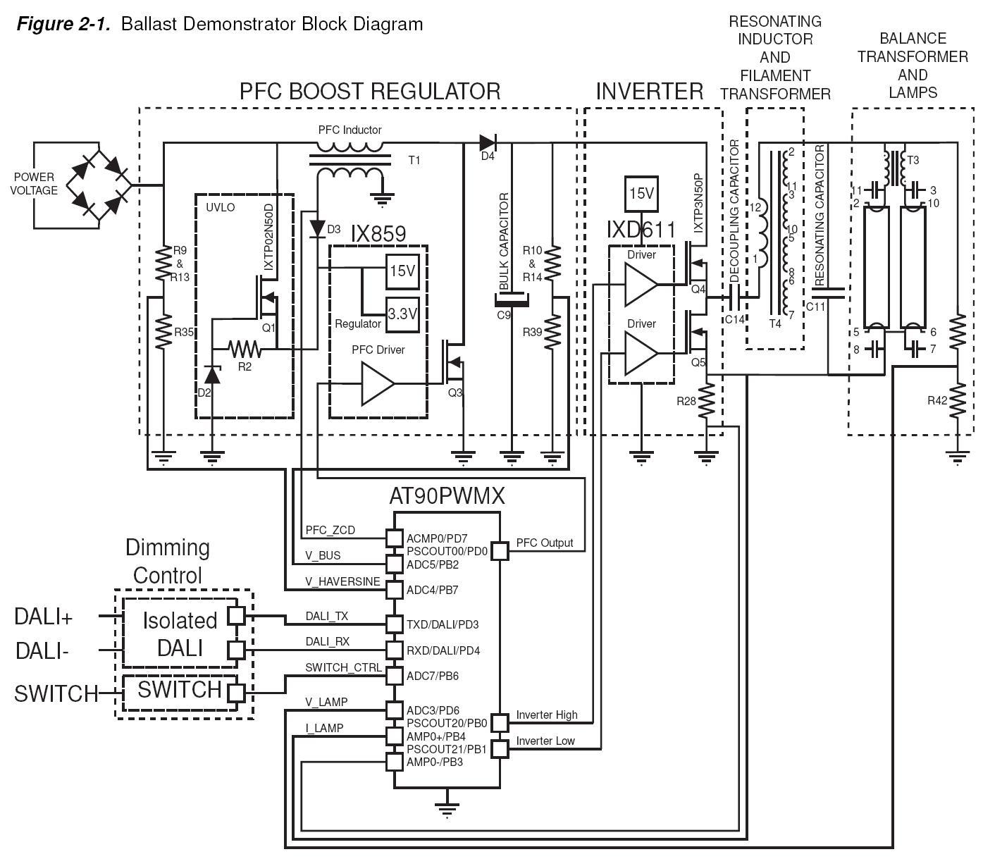
Fluorescent ballast topology usually includes line conditioning for CE and UL compliance, a power factor correction block including a boost converter to 400 V for universal input applications and a half bridge inverter.

Lighting
>
CFL Ballasts
NCP5106BA36WGEVB: 36W CFL Driver, 120V or 230V
Manufacturer:
onsemi
This document describes how the NCP5106B driver can be implemented in a ballast application.

Lighting
>
CFL Ballasts
NCP5104BA36WGEVB: 36W CFL, 85 ~ 145V/184 ~ 265VAC in
Manufacturer:
onsemi
This document describes how the NCP5104 driver can be implemented in a ballast application.
3 Results - Page 1/1