


Have You Thought About Connector Mating Cycles Lately?
No, this isn’t some sly joke about how, if left alone at night, your connectors will magically spawn to create new mini-versions of themselves or miraculously grow new contact positions. Instead, it’s a serious issue that is easily overlooked and ignored until it hits the designer with frustrating consequences during debugging, long-term evaluation, or even in the field.
Connectors are meant to be plugged (mated) and unplugged (unmated), that’s their role. But how many such mating cycles can the connector pair tolerate before performance degrades with high resistance or intermittent contacts, leading to hard-to-trace system problems? Designers may not give much initial thought to a connector’s ratings for mating cycles, which can range from low double-digits to thousands of cycles depending on the product, its users, and the application. But they should. Especially for consumer applications, and when using a connector during the prototyping and development cycle.
Vendors provide specifications for their connectors for some number of such cycles. These specifications are a function of overall connector design, as well as contact design, material, and plating, and within defined voltage and current values. Yet it is easy to exceed that cycle number in the rough and tumble of design debug and evaluation. The consequences range from manageable, such as increased insertion force, to frustrating, such as intermittent connections.
Connectors: too often taken for granted
The physical contact looks simple enough but it is not. Connector performance includes the basic parameters of contact resistance and mating/unmating force, both of which should be low and stay that way (unless it’s a locking connector pair, of course). The contact is a precisely formed metal finger-like structure in most cases. An exception is using the pc board edge as the male mating half. For non-power handling signal-contact designs, the contact is almost always plated with a few micrometers (µm) of gold or tin (less expensive) to reduce electrical resistance, minimize corrosion, and resist wear at the mating surfaces. That is asking a lot of a physically small contact with an even smaller contact area.
How many mating cycles are needed in a connector? The answer depends on the application. In some cases, it is in the low double-digits, but it can also be in the hundreds and thousands (think of that USB connector on your phone). A connector designed to function properly at one end of the cycle-count range is different in basic design, construction, material, and plating than one for the other end. It’s not a reflection on connector quality; it’s a function of being properly matched to the requirements.
Examples show connectivity diversity
A brief look at some representative connectors shows the range of cycles and contact resistances they offer:
• The JAE Electronics SM3ZS067U410AMR1000 is a 67 position, female card edge connector that is compatible with the PCI-SIG M.2 specification, with a contact pitch of 0.020 inch (in.)/0.50 millimeter (mm) (Figure 1). It is rated for 60 mating cycles with 55 milliohms (mΩ) maximum contact resistance.
 Figure 1: The SM3ZS067U410AMR1000 card edge connector from JAE Electronics has contacts on a 0.50 mm pitch, meeting the PCI-SIG M.2 specification, and is rated for 60 mating cycles. (Image source: JAE Electronics)
• In contrast, the Hirose Electric Co Ltd UX60A-MB-5ST, a surface mount, right angle, mini-B USB 2.0 receptacle connector (5-position), is specified for 5000 cycles and 70 mΩ maximum resistance (Figure 2).
 Figure 2: The UX60A-MB-5ST consumer-focused USB receptacle from Hirose is rated for 5000 cycles while maintaining a maximum of 70 mΩ of contact resistance. (Image source: Hirose Electric)
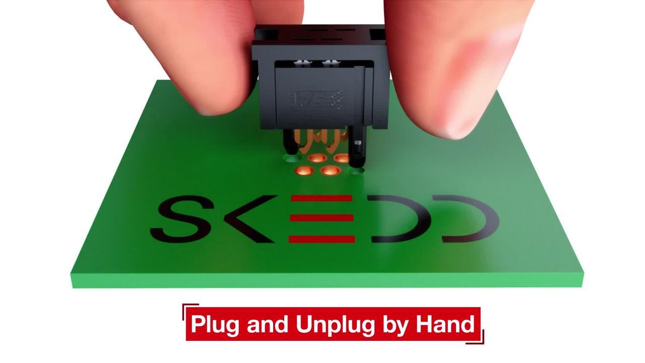
• As flat ribbon cable connectors (also called an insulation displacement connector, or IDC), members of Würth Elektronik’s 490107671012 SKEDD family are normally used within the product enclosure, and don’t require as many mating cycles as a user-accessible connector (Figure 3). This 10 position connector is unique in that it fits directly into plated holes in the pc board rather than using a complementary mating part. Using the vendor-specified board hole pattern, diameter, and plating, it is rated for 10 cycles at 20 mΩ for production runs. Würth also defines a slightly different, more rugged set of numbers for prototyping which boosts that rating to 25 cycles.
 Figure 3: The 490107671012 insulation displacement connector from Würth Elektronik is rated for 10 cycles and has two direct to pc board drill patterns: one for prototypes and one for final products. (Image source: Würth Elektronik)
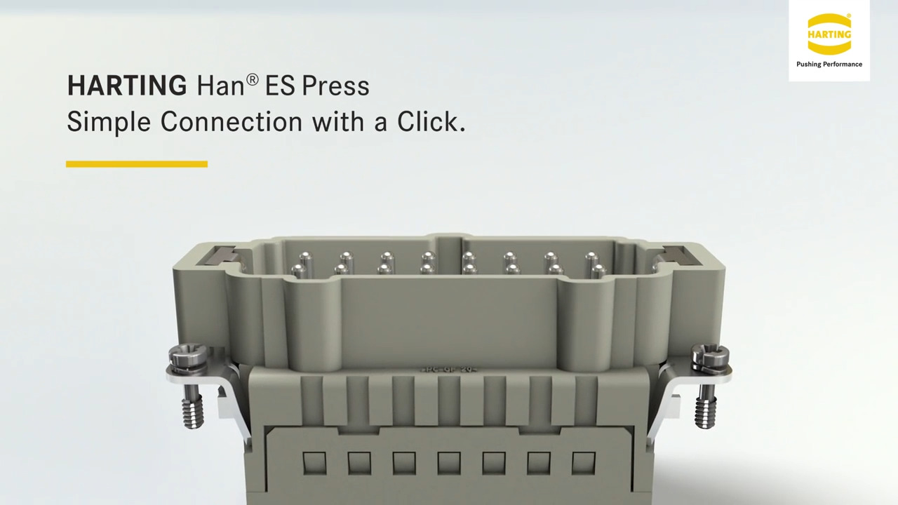
• Finally, the Harting 09332062648 six-contact, ground-position connector for wires with diameters from 0.14 to 2.5 mm² (AWG 26 to AWG 14) has contacts that can handle up to 500 volts at 16 A (Figure 4). Assuming frequent connect/disconnect cycles, it is designed to handle over 10,000 cycles with just 3 mΩ maximum contact resistance.
 Figure 4: The 09332062648 power connector assembly from Harting is specified to maintain contact resistance below 3 mΩ up to at least 10,000 mating cycles. (Image source: Harting)
This array of disparate connectors demonstrates how vendors tailor their connector mating cycle and maximum resistance ratings to the target application. Note that these numbers may not be obvious solely from their physical size or appearance.
Breadboard, prototype, and debug: a different connector life
A connector encounters a very different operating scenario in a product design phase compared to its end-use application role. Many years ago, I was involved in a project which used a standard form factor pc board which plugged into a card cage. We were having all sorts of mysterious issues during debugging, which we eventually discovered was due to the large number of insertion/removal cycles the board underwent at the bench.
An extender board would have reduced the mating cycles as it would have allowed us to access the board “live”, but it degraded signal integrity. Our crude but effective solution was to take the card cage, cut off its top side, and insert our board in the top slot so we could access it while it was in the cage; in fact, we could probe, calibrate, and trim the analog channels while it was in its working environment. That improvised solution worked for us, but it is not applicable to most other projects.
The right selecting strategy can minimize connector problems
What can you do when choosing a connector, especially one that will be subject to many mating cycles in the test phase?
1: First, do your homework: study datasheets with special attention to how and under what conditions the vendor specifies the numbers of mating cycles (there is no industry standard): is it a specified increase in contact resistance? Insertion force? Other?
2: Use an extender, if possible (it often isn’t, but it might be).
3: If using the pc board edge with fingers as one half of the connector pair, work with the board fabricator to determine what sort of extra or special plating is needed (the board’s one or two ounce unplated copper may not work well for long).
4: Consider using a more rugged two-piece connector rather than pc board edge fingers, if possible.
5: Check if the connector vendor offers thicker connector contact plating as a standard or custom option, as many do (also consider if it makes sense for the final bill of materials).
6: For cables, see if you can use a short, easily replaceable “cheat” extension to reduce wear on the primary connector (Figure 5).
7: Finally, identify the potential problems and try to minimize mating cycles (of course, easier said than done).
 Figure 5: You may be able to use a short extension cable to minimize mating cycles of the fixed connector at the product. (Image source: Bill Schweber)
Conclusion
Connectors are generally reliable when used within their defined specifications. However, it’s easy to overlook their limits and exceed their ratings for mating cycles and other parameters, especially in the debug and evaluation stages. The result can be frustrating intermittent problems and inexplicable circuit misbehavior. Take the time to think about how the connector will be used during this phase and develop a set of tactics to avoid problems.
Further Reading:
“Use Direct Plug-in Insulation Displacement Connectors to Streamline Assembly and Lower BOM”
https://www.digikey.com/en/articles/use-direct-plug-in-insulation-displacement-connectors
“Simplify Industrial Equipment Deployment Using Configurable Modular Connectors”
关于此作者

Bill Schweber 是一名电子工程师,撰写了三本关于电子通信系统的教科书,以及数百篇技术文章、意见专栏和产品特性说明。他担任过 EE Times 的多个特定主题网站的技术管理员,以及 EDN 的执行编辑和模拟技术编辑。
在 Analog Devices, Inc.(模拟和混合信号 IC 的领先供应商)工作期间,Bill 从事营销传播(公共关系),对技术公关职能的两个方面均很熟悉,即向媒体展示公司产品、业务事例并发布消息,同时接收此类信息。
担任 Analog 营销传播职位之前,Bill 在该公司颇受推崇的技术期刊担任副主编,并且还在公司的产品营销和应用工程部门工作过。在此之前,Bill 曾在 Instron Corp. 工作,从事材料测试机器控制的实际模拟和电源电路设计及系统集成。
他拥有电气工程硕士学位(马萨诸塞州立大学)和电气工程学士学位(哥伦比亚大学),是注册专业工程师,并持有高级业余无线电许可证。Bill 还规划、撰写并讲授了关于各种工程主题的在线课程,包括 MOSFET 基础知识、ADC 选择和驱动 LED。

Have questions or comments? Continue the conversation on TechForum, Digi-Key's online community and technical resource.
Visit TechForum相关博客


此作者发布的其它博客


 中国
中国