


How to Power and Control Brushless DC Motors
投稿人:DigiKey 北美编辑
2016-12-07
The brushless DC (BLDC) motor’s increasing popularity is due to the use of electronic commutation. This replaces the conventional mechanics comprised of brushes rubbing on the commutator to energize the windings in the armature of a DC motor.
Electronic commutation provides greater efficiency over conventional DC motors with improvements of 20 to 30% for motors running at the same speed and load. As the International Energy Agency reports that 40% of all global electricity is used to power electric motors, such efficiency gains become compelling.
Further, the BLDC motor is more durable. It retains its high performance while the efficiency and power of an equivalent conventional motor declines due to wear, causing poor brush contact, arcing between the brushes and the commutator dissipating energy, and dirt compromising electrical conductivity.
Greater efficiency allows BLDC motors to be made smaller, lighter and quieter for a given power output, further increasing their popularity in sectors such as automotive; white goods; and heating, ventilation and air conditioning (HVAC). Other advantages of BLDC motors include superior speed versus torque characteristics (with the exception of torque at start-up), a more dynamic response, noiseless operation, and higher speed ranges.
The downside of BLDC motors is their complexity and the associated increase in cost. Electronic commutation demands supervisory circuits to ensure precise timing of coil energization for accurate speed and torque control, as well as ensuring the motor runs at peak efficiency.
Fortunately, this sector is rapidly maturing and silicon vendors now offer a wide range of highly-integrated BLDC motor driver power MOSFET chips with either external or embedded microcontrollers to simplify the design process, while also lowering component costs. This article will explain how the designer can take advantage of these latest chips to ease the design process
BLDC motor basics
All electric motors, whether mechanically or electronically commutated, adhere to the same basic method of converting electrical energy into mechanical energy. Current through a winding generates a magnetic field, which in the presence of a second magnetic field (typically initiated by permanent magnets) generates a force on that winding that reaches a maximum when its conductors are at 90° to the second field. Increasing the number of coils raises the motor output and smooths power delivery. (Monolithic Power Systems (MPS) has produced an application note (see Reference 1) which nicely summarizes motor fundamental concepts.)
A BLDC motor overcomes the requirement for a mechanical commutator by reversing the motor set-up; the windings become the stator and the permanent magnets become part of the rotor. The stator is typically comprised of steel laminations, slotted axially to accommodate an even number of windings along its inner periphery. The rotor consists of a shaft and a hub with permanent magnets arranged to form between two to eight pole pairs that alternate between ‘N’ and ‘S’. Figure 1 shows one example of a common magnet arrangement, in this case two magnet pairs bonded directly to the rotor hub.

Figure 1: In a BLDC motor the permanent magnets are attached to the rotor. Typical configurations comprise between two and eight pairs alternating between ‘N’ and ‘S’ poles. (Courtesy: MPS)
Because the windings are stationary, permanent connections can be established to energize them. In order for the stationary windings to move the permanent magnet, the windings need to be energized (or commutated) in a controlled sequence to produce a rotating magnetic field.
Because the rotating magnetic field generated by the stator causes the rotor to revolve at the same frequency, a BLDC motor is known as a “synchronous” type. BLDC motors can come in one-, two-, or three-phase. Three-phase BLDC motors are the most common and will be the subject of the rest of this article.
BLDC motor control
By far the most common configuration for sequentially applying current to a three-phase BLDC motor is to use three pairs of power MOSFETs arranged in a bridge structure, as shown in Figure 2. Each pair governs the switching of one phase of the motor. In a typical arrangement, the high-side MOSFETs are controlled using pulse-width modulation (PWM) which converts the input DC voltage into a modulated driving voltage. The use of PWM allows the start-up current to be limited and offers precise control over speed and torque. The PWM frequency is a trade-off between the switching losses that occur at high frequencies and the ripple currents that occur at low frequencies, and which in extreme cases, can damage the motor. Typically, designers use a PWM frequency of at least an order of magnitude higher than the maximum motor rotation speed.

Figure 2: A three-phase BLDC motor is typically powered by three pairs of MOSFETs arranged in a bridge structure and controlled by PWM. PWM offers precise control over the motor’s speed and torque. (Diagram drawn using DigiKey Scheme-it®)
There are three control schemes for electronic commutation: trapezoidal, sinusoidal and field-oriented control. The trapezoidal technique (described in the example below) is the simplest. At each step, two windings are energized (one “high” and one “low”) while the other winding floats. The downside of the trapezoidal method is that this ‘stepped’ commutation causes the torque to ‘ripple’, especially at low speeds.
Sinusoidal control is more complex, but it reduces torque ripple. During this control regime, all three coils remain energized with the driving current in each of them varying sinusoidally at 120° from each other. The result is a much smoother power delivery compared with the trapezoidal technique.
Field-oriented control relies on measuring and adjusting stator currents so that the angle between the rotor and stator flux is always 90°. This technique is more efficient at high speeds than the sinusoidal method and gives better performance during dynamic load changes compared to all other techniques. There is virtually no torque ripple, and smoother, accurate motor control can be achieved at both low and high speeds.
This article will limit the rest of the technical discussion to the trapezoidal technique.
In a motor employing a trapezoidal control scheme, the MOSFET bridge switching must occur in a precisely defined sequence for the BLDC motor to operate efficiently. The switching sequence is determined by the relative positions of the rotor’s magnet pairs and the stator’s windings. A three-phase BLDC motor requires a six step commutation sequence to complete one electrical cycle. The number of mechanical revolutions per electrical cycle is determined by the number of pairs of magnets on the rotor. For example, two electrical cycles will be required to mechanically spin a rotor comprised of two pairs of magnets one revolution.
Sensored vs. sensorless
Two technologies offer a solution for positional feedback. The first and most common uses three Hall-effect sensors embedded in the stator and arranged at equal intervals, typically 60° or 120°. A second, ‘sensorless’ control technology comes into its own for BLDC motors that require minimal electrical connections.
In a sensor-equipped BLDC motor, each Hall-effect sensor is combined with a switch which generates a logic “high” (for one magnetic pole) or “low” (for the opposite pole) signal. The commutation sequence is determined by combining the logic signals from the Hall-effect sensors and associated switches. At any time, at least one of the sensors is triggered by one of the rotor’s magnetic poles and generates a voltage pulse.
Figure 3 illustrates the commutation sequence of a three-phase BLDC motor driven anti-clockwise. The Hall-effect sensors are mounted at positions “a”, “b” and “c”. For each step in the commutation sequence, one winding (either “U”, “V” or “W”) is driven high by the MOSFET bridge while one is driven low and the third is left floating. For example, at the top left of the figure, U is high (forming an N pole), V is low (S) and W is floating. The resulting magnetic field moves the rotor anti-clockwise as its permanent magnets are repelled by one winding and attracted by the next. The second stage (below) shows winding U remaining high while V switches to floating and W switches low thus maintaining the ‘rotation’ of the magnetic field and moving the rotor with it. The remaining commutation steps, one electrical cycle, completes half a mechanical rotation of the rotor.
")
Figure 3: Electronic commutation sequence for three-phase BLDC motor using MOSFET bridge and Hall-effect sensors. In this case the rotor is driven anti-clockwise and the Hall-effect sensors (‘a’, ‘b’ and ‘c’) are mounted at 60° intervals. (Courtesy: MPS)
Figure 4 shows the status of the phase windings in relation to the Hall-effect sensor signals for the anti-clockwise spinning motor shown in Figure 3 above.

Figure 4: Hall-effect sensor logic switch output and winding status timing diagram for three-phase BLDC motor driven anti-clockwise. Note how at least one logic switch and winding changes status every 60°. (Courtesy: MPS)
A sensorless BLDC motor makes use of the electromotive force (EMF) that gives rise to a current in the windings of any DC motor with a magnetic field that opposes the original change in magnetic flux as described by Lenz’s Law. The EMF tends to resist the rotation of the motor and is therefore referred to as “back” EMF. For a given motor of fixed magnetic flux and number of windings, the EMF is proportional to the angular velocity of the rotor.
By monitoring the back EMF, a suitably programed microcontroller can determine the relative positions of the stator and rotor without the need for Hall-effect sensors. This simplifies motor construction, reducing its cost as well as eliminating the additional wiring and connections to the motor that would otherwise be needed to support the sensors, thus improving reliability.
However, because a stationary motor generates no back EMF, the controller is unable to determine the motor position at start-up. The solution is to start the motor in an open loop configuration until sufficient EMF is generated for the controller to determine rotor and stator position and then take over supervision. A more sophisticated control regime is used if the motor is used in an application where reverse rotation is forbidden.
The back EMF generated by each winding of the BLDC motor described above is shown in the bottom half of Figure 5. This is compared to the Hall-effect sensor logic switch output for a comparable BLDC motor equipped with sensors. It can be seen from the figure that the zero crossing points for the EMF generated in winding coincide with the switching status changes for the logic switches. It is this zero-crossing information that the microcontroller uses to trigger each stage of the commutation cycle in a sensorless BLDC motor. (See the library article “Controlling Sensorless, BLDC Motors via Back EMF”.)

Figure 5: Hall-effect sensor logic switch output compared with winding back EMF for a BLDC motor driven anti-clockwise. Note how the zero-crossing points for the back EMF information used to control a sensorless BLDC motor coincide with the change in status of the logic switches in a BLDC motor equipped with sensors. (Courtesy: MPS)
Designing a BLDC motor
While the principles of BLDC motor commutation are involved, BLDC motor power and control circuit design needn’t be. There are plenty of proven integrated products on the market that can be used as the building blocks for the circuitry. BLDC power modules containing either gate drivers or integrated MOSFETs lie at the heart of the circuit.
Allegro Microsystems’ A4915 three-phase MOSFET driver operates as a pre-driver for a six-power MOSFET bridge for a BLDC motor. This device is designed for battery-powered products. One notable feature for saving power is a low power sleep mode which ensures the device draws minimal current when not turning the motor. The device also features synchronous rectification, a technique borrowed from switching voltage regulators to lower power consumption and eliminate the need for external Schottky diodes.
Microchip also offers a pre-driver for a six-power MOSFET bridge for a BLDC motor, but this time for small sensorless units used in automotive, home appliances and hobby products. The MCP8025 device integrates a step-down (“buck”) switching regulator to power an external controller in addition to two low drop out (LDO) linear regulators and a charge pump to power the MOSFET bridge.
This chip keeps things simple by measuring the back EMF of the floating winding which is then compared to the motor’s neutral point. When the back EMF crosses the zero point, the zero-crossing detector sends a signal to the host controller to indicate the commutation reference point.
Texas Instruments’ DRV8313 takes things a step further by integrating three individually controllable half-H bridge drivers. The advantage of this arrangement is that as well as being used for three-phase BLDC motor control, the chip can be used to drive a mechanically-commutated motor (using two of the half-H bridges) or three independent solenoids. The chip can supply up to 3.5 A from an 8 to 60 V supply.
The DRV8313 does not include sensor inputs. TI suggests that for either sensored or sensorless operation, the chip should be teamed with a microcontroller such as the popular MSP430. Such an arrangement, as illustrated in Figure 6, provides a complete closed-loop control system for a sensored, three-phase BLDC motor.

Figure 6: A complete closed-loop control system for a sensored three-phase BLDC motor. The circuit comprises an analog speed input, MSP430 microcontroller supervising the PWM outputs for the power MOSFETs, a six MOSFET bridge driver, MOSFET bridge and BLDC motor. Motor stator and rotor positions are determined by three Hall-effect sensors which feed signals to the microcontroller. (Courtesy: Texas Instruments)
TI offers an alternative part, the DRV8308, which doesn’t integrate the MOSFETs. It can, however, take inputs from three Hall-effect sensors directly, and therefore can be used without an additional microcontroller if preferred.
While Hall-effect sensors are a proven solution for positional feedback, developments in position sensor technology offer greater precision and the promise of a more efficient commutation sequence. For example, Analog Devices’ ADA4571 is an angle sensor and signal conditioner that can replace the three Hall-effect sensors of a typical three-phase BLDC motor design with a single device. The advantages are space savings and the need to work only with a single signal.
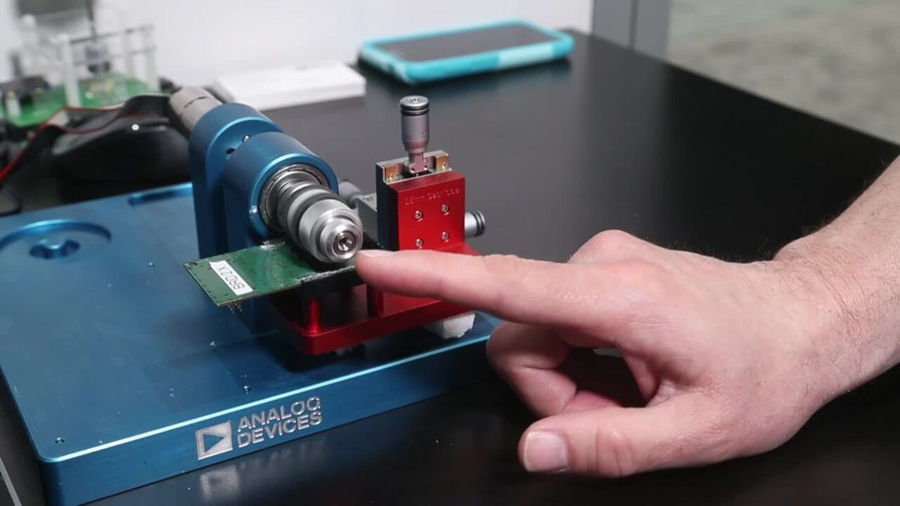
The ADA4571 uses anisotropic magnetoresistive (AMR) technology. A typical implementation is to mount a diametrically magnetized disc on the end of the BLDC motor’s shaft (see Figure 7). The disc’s magnetic field passes through the plane of the sensor and the rotor angle is determined without contact between the mechanical and electrical components.

Figure 7: A single anisotropic magnetoresistive sensor can placed adjacent to a disc magnet mounted on the BLDC motor shaft end, replacing three Hall-effect sensors for BLDC motor angle sensing, saving space and easing signal processing.
The ADA4571 delivers amplified cosine and sine output signals related to the angle of the rotating magnetic field. The output voltage range is ratiometric to the supply voltage. Analog Devices suggest teaming the sensor with an AD7866 12-bit ADC to convert the ADA4571’s analog signals to the digital signal required by the BLDC’s motor drive controller or external microcontroller.
Analog Devices claims that the use of a single angle sensor doesn’t compromise commutation precision as the ADA4571 is capable of limiting sensed angular error to a maximum of +/-0.25° for BLDC motor speeds up to 25,000 rpm.
Conclusion
The electronic commutation of BLDC motors demands precise control, adding complexity and cost to the motor’s circuitry. However, the returns in efficiency such as reduced power, reliability, and space, and weight savings of the final product more than offset these drawbacks. Further, a wide range of proven, integrated BLDC motor drivers significantly ease the design process while adding flexibility for the designer to fine-tune a design for a specific application.
References:
- “Brushless DC Motor Fundamentals,” Jian Zhao and Yangwei Yu, MPS Application Note (AN047), July 2011.
免责声明:各个作者和/或论坛参与者在本网站发表的观点、看法和意见不代表 DigiKey 的观点、看法和意见,也不代表 DigiKey 官方政策。


 中国
中国