Accelerate Test and Troubleshooting of I²C and Other Common Serial Data Streams
投稿人:DigiKey 北美编辑
2017-10-31
Microcontrollers are used in embedded systems ranging from toys to advanced aircraft, though they typically are used to execute specialized operations in a more complex system. These embedded controllers need to communicate with other system components using complex serial interfaces and protocols that, while commonplace, can be difficult to verify and troubleshoot.
These data communication protocols include inter-integrated circuit, (I²C), serial peripheral interface (SPI), and universal asynchronous receiver transmitter (UART). Verifying and troubleshooting these serial data links can require multiple instruments, including ones to measure and confirm the physical layer interface, and others to verify data content and handshaking. This can add to the cost of test, consume bench top space, and become unwieldy.
The alternative is to opt for oscilloscopes that combine multiple functions, such as Teledyne LeCroy’s HDO4104A high-definition line of oscilloscopes. These offer serial data trigger and decode options that combine the power of an oscilloscope for physical layer analysis and troubleshooting, with protocol analysis. This combination of measurement tools in a single instrument can greatly accelerate the design verification cycle by providing shorter test and debug times.
This article will show how to use the HDO4104A effectively, using the I²C bus as an example, though the tools and techniques used here are applicable to other common low-speed serial buses like SPI and UART.
Typical microcontroller interfaces
A typical microcontroller communicates with other devices using a number of serial interfaces, such as I²C, SPI, UART, CAN, and LIN (Figure 1). I²C and SPI generally communicate between the microcontroller and a peripheral in the same controller board. UART, CAN, and LIN are used to transfer data from one microcontroller to another.

Figure 1: A typical microcontroller uses multiple serial buses to communicate with both internal and external devices. (Image source: DigiKey)
The I²C serial interface
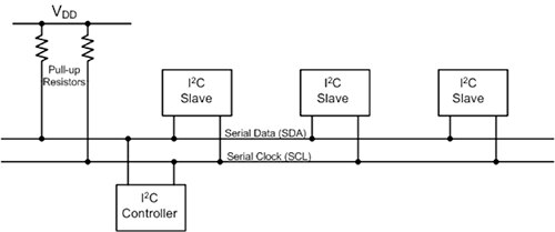
I²C is a synchronous master/slave communication protocol that supports multiple masters. The serial interface uses two bidirectional lines, clock (SCL) and data (SDA), for signaling at data rates up to 3.4 Mbits/s (Figure 2).

Figure 2: A block diagram of a representative I²C serial interface showing the interconnection of the master and slave devices using the bidirectional SDA and SCL lines. (Image source: DigiKey)
The packet structure for I²C
Each I²C device uses a unique 7- or 10-bit address. The master initiates transfers using a start bit (Figure 3). This is followed by the address of the destination device. A read/write bit indicates the direction of the transfer.

Figure 3: The packet structure of the I²C serial interface begins with a master-initiated Start bit, followed by the address bits and the read/write bit. These are acknowledged by the receiver. Data content follows, in 8-bit bytes, with each data byte being acknowledged. (Image source: Teledyne LeCroy)
The addressed slave device confirms receipt using an acknowledge bit (ACK). Multiple data segments follow with the direction determined by the R/W bit. Each data segment is acknowledged by the receiving device. If ACK is not asserted by the receiver, the transmitter will restart and transmit the data again. Transmission stops with the assertion of the stop bit.
The oscilloscope’s view of I²C
The HDO4104A oscilloscope, equipped with the HDO4K-I2CBUS TD I²C Bus Trigger Decode option, provides a view of multiple I²C packets (Figure 4).
Figure 4: Viewing multiple I²C packets on a Teledyne LeCroy HDO4104A with the I²C bus decode option. Note that the option supports up to four simultaneous decodes. (Image source: DigiKey)
The dialog box at the bottom of the figure shows the decode setup for the I²C protocol. The data source is identified as channel 1, while the clock source is channel 2. Note that the clock does not have to be displayed for the decoder to operate. Data source can be channel or logic inputs. The decoder offers the option of displaying data content in binary, hexadecimal, or ASCII characters. Hex has been selected. An additional tab provides controls for setting data and clock levels and hysteresis.
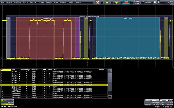
The scope has captured multiple I²C packets. The upper trace (C1) shows the contents of the data line (SDA). The lower trace (C2) is the clock line (SCL); the decoder automatically detects the clock frequency. The table below the traces lists the device address and data content of each acquired packet, along with the address length, R/W state, packet length, and the time from the trigger to the Start of Frame.
The contents of the table are user configurable using the Configure Table button in the Decode dialog box. The table is interactive, and pointing and clicking on any table entry will cause the scope to zoom in on the selected packet (Figure 5). A color coded overlay is projected over the data waveform identifying the key elements of the packet. The address field is in red and the data segments are overlaid in blue.
Figure 5: An expanded (zoom) view showing the color-coded overlay identifying the key elements of a single I²C data packet. (Image source: DigiKey)
The device address and data content are decoded using an advanced software algorithm and displayed above the waveform. Automatic decoding is a big time saver compared to manual decoding of 1’s and 0’s from the raw digital waveform.
The table shows the selected packet highlighted, while all the other packets in the table are still displayed. The length of the table is user selectable, or it can be turned off.
The color overlay is scaled to the displayed data. As the zoom trace is expanded, the overlay adds additional detail to the display (Figure 6). Here, as the space becomes available, the Start (violet), R/W (purple), and ACK (yellow) bits have been highlighted and labeled.
Figure 6: Expanding the trace horizontally adds more detail to the overlay. In this figure, the Start (violet), R/W (purple), and ACK (yellow) bits have been highlighted and labelled. (Image source: DigiKey)
In addition to using the decode table to search for specific events, the decode function includes a search engine that can locate I²C packets based upon the index (IDX), time, address length, device address, R/W state, packet length, data content, and status. An advanced status search broadens the search to accommodate and/or logic operations, based on the contents of up to three of the table columns.
Serial triggering
The serial data and trigger option include advanced serial triggering implemented directly in the scope’s hardware. The scope searches the data stream in real-time looking to recognize the user defined serial conditions. When the pattern is identified, the oscilloscope is triggered and the waveforms on all the selected channels are acquired. The trigger engine is independent of the decode function and each can be used separately. Selecting ‘Link to Trigger’ in the serial decode dialog box links the trigger and decode functions so that settings common to both are tracked when changed in either.
The trigger types available for I²C include triggering on basic operation such as Start, Stop, Restart, and No Ack. Data-dependent triggers include device address, device address plus data, frame length, and EEProm data patterns.
An example of a basic trigger using the No Ack trigger type will trigger the scope when data is not recognized by the receiver (Figure 7). The scope trigger point is indicated by an inverted caret symbol beneath the trace display. The expanded decoded view shows it on the extreme right, where the read overlay marked the missing Ack signal condition.
Figure 7: The I²C trigger setup for a No Ack condition triggers the scope when the data transfer is not acknowledged by the receiver. (Image source: DigiKey)
A more complex trigger is based on the device address and data content (Figure 8).
Figure 8: The I²C trigger setup for device address and data content. The scope triggers when the Hex address 4C is active and the data content equals Hex 65. This allows triggering on a specific data state for a specific device. (Image source: DigiKey)
In this example the oscilloscope is triggered when device Hex 4C is addressed and the data content equals Hex 65. Note the trigger position indicator caret marks the trigger immediately after the data segment containing Hex 65 occurs. The data content trigger is conditional and can trigger based on conditions of equality, non-equality, less than, less than or equal, more than, or more than or equal.
Sometimes, I²C uses data bytes to specify sub-addresses in devices like EEPROM. These sub-addresses allow access to specific memory blocks within the device. Conditional data triggers are useful for triggering on a range of addresses corresponding to these sub-addresses.
Conclusion
The widespread use of I²C, SPI, CAN and LIN make it critical to minimize the time taken to verify, troubleshoot, and debug these communication interfaces. To that end, multipurpose test equipment such as the HDO4104A has become available that, if used correctly as shown here, greatly accelerates the test and debug process. In doing so, they save on time, space, resources and overall cost.

免责声明:各个作者和/或论坛参与者在本网站发表的观点、看法和意见不代表 DigiKey 的观点、看法和意见,也不代表 DigiKey 官方政策。


