


Use a Ready-Made LTE Cat M1 Modem to Simplify Low-Power Wide Area IoT Connectivity
投稿人:DigiKey 北美编辑
2017-11-21
Developers of wide area IoT applications such as mobile health monitoring, remote sensing, and smart cities have a connectivity problem: Bluetooth, zigbee, and Wi-Fi lack the range required, while traditional cellular radios are too costly, power hungry, and complex.
To address this, another connectivity option has emerged, LTE Cat M1 cellular. Along with it have come easy-to-use, certified solutions that greatly reduce the complexity and cost of cellular connectivity, while accelerating time to market for wide area, low-power, low-cost, long-range IoT designs.
One such solution is NimbeLink’s NL-SW-LTE-SVZM20 Skywire LTE Cat-M1 modem. This article will describe the NL-SW-LTE_SVZM20 and how to start designing it in and programming it.
LTE Cat M1 basics
LTE Category M1 was created as a less expensive alternative to more conventional LTE services such as Cat 4, which was designed to support throughput at 100 Mbits/s. For ultra-low-power, low-cost IoT sensing applications with low duty cycles and data-rate needs in the 10s or 100s of Kbits/s, this is clearly overkill. In Release 13 of the LTE standard, 3GPP (3rd Generation Partnership Project) defined a class of LTE technologies including LTE Cat M1, with data rates below 300 Kbits/s.
This lower data rate, and its resulting reduction in complexity, better matches IoT design requirements, while still allowing designers to take advantage of cellular’s ubiquity and relatively interference-free licensed band operation. It’s now possible for a long-range IoT device to operate on a single battery for years without replacement or recharge.
In addition, LTE Cat M1 offers sufficiently high performance that IoT devices can transmit data bursts quickly and return rapidly to low-power states. Also, LTE Cat M1 has latencies in the 10 ms range, allowing its use in IoT applications with time critical requirements.
Finally, LTE Cat M1 supports voice over LTE (VoLTE) connectivity needed to support an expected growth in demand for voice-based interfaces in IoT applications such as health and fitness, retail, transportation, building services, and many more.
Meeting LTE design and certification challenges
While it has clear advantages, LTE connectivity does have multiple challenges. At the design level, LTE chip sets are still relatively complex devices with stringent requirements for optimizing transmitter and receiver signal paths.
Manufacturers address these concerns by offering LTE modules that combine chip sets with optimized RF circuit designs, typically leaving system interface requirements such as signal-voltage translation and buffering to the system designer. LTE modem providers meet these requirements with boards that surround the module with the final elements needed to speed integration in a system design such as an MCU-based IoT device.
The hierarchical nature of cellular solutions also addresses a final requirement that can halt production of even a well-designed cellular-based system. Developers need to conform to governmental and carrier requirements through certification testing that can add months and significant cost to an otherwise completed design. Products lacking proper certification are simply not allowed onto the carrier network.
At higher levels of the cellular solution hierarchy, use of uncertified components compounds these costs. For example, a module manufacturer using chip sets that lack carrier certification faces significantly higher costs and delays as certification labs fill in the gaps in testing. A further complication arises because certification earned just from a governmental body or just from the carrier does not ensure certification from another. In the US, for example, carriers often levy additional testing requirements beyond those specified by the Federal Communications Commission (FCC).
NimbeLink removes both of these design and certification barriers with its NL-SW-LTE-SVZM20 Skywire LTE Cat-M1 modem.
Rapid development with ready-to-go modem subsystem
Designed specifically for IoT applications, the modem features low-power operation while supporting LTE Cat M1 Verizon services at LTE Bands B4 and B13. Operating at center frequencies around 1700 MHz and 750 MHz, respectively, B4 and B13 can offer deep coverage to IoT devices operating with relatively low link budgets. Just as important for developers, the modem comes pre-certified for end devices, eliminating the costs and delays associated with cellular certification. At the same time, NimbeLink’s Skywire modems support firmware upgrades, enabling developers to deploy new features in the field as they emerge in carrier networks.
For IoT developers, the NimbeLink modem combines an LTE Cat M1 module with support functionality to provide a full cellular subsystem (Figure 1). As a result, developers work with a simple interface for systems integration, functionally connecting their MCU-based system to the modem using familiar “AT” commands through the shared UART hardware interface.

Figure 1: The NimbeLink NL-SW-LTE-SVZM20 Skywire LTE Cat-M1 modem combines an LTE Cat M1 module with features and functions designed to simplify integration in system designs. (Image source: NimbeLink)
Physical design integration is just as simple. Within the modem’s 29 x 33 x 10.5 mm footprint, its I/O pin placement conforms to the industry standard XBee form factor, allowing designers to combine the modem with compatible boards. Designers can take advantage of the XBee compatible pin arrangement using a pair of 10-pin connectors such as the Sullins Connector Solutions NPPN101BFCN-RC to attach the modem to their own board. NimbeLink also provides a recommended footprint that engineers can use to solder the modem to their boards (Figure 2). Developers complete physical integration using an LTE-compatible antenna such as the Taoglas FXP400.07.0100A.

Figure 2: The NimbeLink NL-SW-LTE-SVZM20 Skywire LTE Cat M1 modem provides an XBee-compatible pin interface for connecting to compatible boards or soldering to custom boards using the footprint specifications shown here. (Image source: NimbeLink)
LTE subsystem
NimbeLink demonstrates the details of interface design and system integration for the modem with its NL-M1DK development kit. While the development board offers a complete LTE Cat M1 solution, the associated schematics illustrate the simple interface required to integrate the modem into a custom system design (Figure 3).
")
Figure 3: NimbeLink provides detailed schematics for interfacing its NL-SW-LTE-SVZM20 Skywire LTE Cat-M1 modem to an IoT design, including MOSFET buffers and a current measurement test point. (Image source: NimbeLink)
As the schematic illustrates, the module requires only a few additional components to add LTE Cat M1 capability to an MCU-based design. Along with a handful of resistors and capacitors, NimbeLink adds a pair of ON Semiconductor FDV301N MOSFET buffers. NimbeLink also adds a Susumu RL1220S-R10-F surface-mount current-sense resistor to the development board to allow developers to measure modem current across the board’s J13 connector.
Besides evaluating LTE Cat M1 connectivity, developers can use the board to prototype a basic battery powered IoT sensor system. The board includes a battery management circuit built around the Texas Instruments BQ25060DQCR. As a result, developers can simply plug in a rechargeable source such as the SparkFun Electronics PRT-13855 2 Ah @ 3.7 volt (nominal) lithium battery to power the board in a standalone configuration. On-board LEDs and buttons support a simple user interface, while the board’s Everlight Electronics PT15-21C/TR8 encapsulates a phototransistor and lens to serve as a self-contained position sensor.
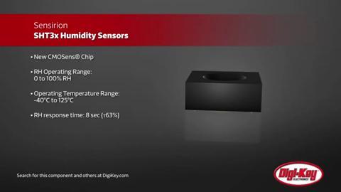
The board’s Sensirion SHT30-DIS-B temperature and humidity sensor provides an additional data source for IoT design evaluation. The SHT30 sensor connects to the system through the I2C interface, which itself is brought out on separate board pins along with the modem UART interface. Finally, the board includes an FTDI FT2232D IC, which provides a USB interface for connection to a development system.
Developers can get started with the development kit simply by attaching the provided antenna, power cable, USB cable, and inserting the NimbeLink NL-SIM-VER-M1 SIM card on the underside of the modem board (Figure 4). As with any mobile device using cellular, developers also need to activate the device on the carrier network. In this case, developers contact NimbeLink support, which performs a quick procedure to activate the modem on the Verizon network, typically on the same day.

Figure 4: Combined with the NimbeLink NL-SW-LTE-SVZM20 modem, the NimbeLink NL-M1DK development kit provides a complete LTE Cat-M1 connectivity subsystem. (Image source: NimbeLink)
Once connected, the device operates on a NimbeLink data plan, using a private IP address within NimbeLink’s private network within Verizon’s network. As a result, the cellular-connected device is unreachable from the public Internet as it can only send data to the Internet. Later, developers can provision a production device with a static IP within their own private network in the Verizon network for two-way communications across the Internet for their IoT application. Whether operating on the NimbeLink private network or their own, the modem uses a simple set of commands to provide its connectivity services.
Network connection
Developers interact with the modem using a series of AT commands, delivered either interactively or programmatically. During development, engineers can connect the board by USB to their host system and issue AT commands using a host terminal program such as PuTTY to interact with the modem.
Although the task of creating an appropriate AT command sequence is simple enough, NimbeLink eliminates that development step. NimbeLink’s open-source library provides developers with a series of scripts that include the specific AT commands required to perform operations such as opening a point-to-point protocol (PPP) connection to the cellular network. Here, a base script provides AT commands that define (CGDCONT) the packet data protocol (PDP) type and user access point name (APN), set phone functionality (FUN), attach to the packet service (CGATT), and execute (CGDATA) the PPP connection (Listing 1).
TIMEOUT 3
ECHO ON
'' AT
OK AT+CGDCONT=3,"IPV4V6","[apn]"
OK AT+CFUN=1
OK AT+CGATT=1
OK AT+CGDATA="ppp",3,1
CONNECT ''
Listing 1: NimbeLink’s open-source script library provides developers with the specific AT command sequences required for basic operations. (Code source: NimbeLink)
Another script calls the base script and performs related operations required to complete the connection (Listing 2).
/dev/ttyUSB0
921600
connect "/usr/sbin/chat -v -f /etc/ppp/peers/vzw-SVZM2x-chat"
noauth
defaultroute
usepeerdns
local
debug
updetach
Listing 2: A NimbeLink script shows developers how to establish cellular connections using other library scripts such as vzw-SVZM2x-chat in this case. (Code source: NimbeLink)
In an application, developers would program the IoT device’s MCU host to transmit a similar AT command stream using the shared UART connection. Having established a PPP connection, the IoT device would interact with a cloud server using the conventional http web protocol or a lightweight messaging protocol such as ISO standard Message Queue Telemetry Transport (MQTT). In turn, an IoT application would typically use this basic PPP-enabled MQTT functionally to establish a secure connection with the cloud using Transport Layer Security (TLS) mutual authentication.
IoT cloud
IoT cloud platforms such as the Amazon Web Services (AWS) support this specific communications stack while providing additional IoT-oriented services. For AWS, developers can access these services through libraries that implement the AWS IoT applications programming interface (API). For example, the AWS IoT Embedded C library includes sample programs that demonstrate basic design patterns used to build custom IoT applications. A sample program illustrates implementation of the basic publish/subscribe model used with MQTT. Here, the sample shows how developers would use the call:
aws_iot_mqtt_publish(&client, "sdkTest/sub", 11, ¶msQOS0);
to publish data to the MQTT broker, using a parameter that instantiates a data structure that holds a description of the MQTT message (Listing 3).
typedef struct {
QoS qos; |
///< Message Quality of Service |
|
uint8_t isRetained; |
///< Retained messages are \b NOT supported by the/// AWS IoT Service at the time of this SDK release. |
|
uint8_t isDup; |
///< Is this message a duplicate QoS > 0 message?/// Handled automatically by the MQTT client. |
|
uint16_t id; |
///< Message sequence identifier. Handled /// automatically by the MQTT client. |
|
void *payload; |
///< Pointer to MQTT message payload (bytes). |
|
size_t payloadLen; |
///< Length of MQTT payload. |
} IoT_Publish_Message_Params;
Listing 3: Developers can build IoT applications on the Amazon Web Services (AWS) cloud, modeling their software on samples provided with the AWS IoT Embedded C library such as this MQTT message structure. (Code source: Amazon Web Services)
The IoT device subscribes to an MQTT topic using a similar call:
aws_iot_mqtt_subscribe(&client, "sdkTest/sub", 11, QOS0, iot_subscribe_callback_handler, NULL);
Because of the asynchronous nature of subscription messages, the MQTT subscribe call includes a callback (iot_subscribe_callback_handler) that handles incoming messages as they appear. The AWS Embedded C sample provides a callback stub that illustrates the input parameters and typical behavior of a callback (Listing 4).
Copy
void iot_subscribe_callback_handler(AWS_IoT_Client *pClient, char *topicName, uint16_t topicNameLen,
                                                              IoT_Publish_Message_Params *params, void *pData) {
       IOT_UNUSED(pData);
       IOT_UNUSED(pClient);
       IOT_INFO("Subscribe callback");
       IOT_INFO("%.*s\t%.*s", topicNameLen, topicName, (int) params->payloadLen, params->payload);
}
Listing 4: Sample software in the AWS IoT Embedded C library illustrates key design patterns such as a callback an IoT device might use for handling asynchronous data associated with subscribed MQTT topics. (Code source: Amazon Web Services)
Developers can use the AWS Embedded C library or similar AWS IoT libraries for C++, Java, and Python, among others, to connect IoT devices to the AWS IoT platform. Within its IoT platform, AWS provides services such as authentication, device shadowing, and rules-based activation among others. Once connected to the AWS IoT platform, applications can take advantage of the more comprehensive set of AWS cloud services for real-time streaming, analytics, monitoring, and more.
Conclusion
LTE Cat M1 offers an increasingly attractive option for low-power, wide area connectivity in a growing number of IoT applications. Unlike earlier cellular technologies, LTE Cat M1 connectivity can meet IoT throughput requirements at reduced system cost, power consumption, and complexity. Using a NimbeLink modem, developers can rapidly implement LTE Cat M1 connectivity with little additional effort in hardware design or software development.
免责声明:各个作者和/或论坛参与者在本网站发表的观点、看法和意见不代表 DigiKey 的观点、看法和意见,也不代表 DigiKey 官方政策。


 中国
中国