New Developments in BLDC Motor Control Solutions
投稿人:电子产品
2013-06-26
The Brushless DC (BLDC) motor is rapidly becoming the natural choice for applications demanding high reliability, high efficiency, and high power-to-volume ratio. The motors provide lots of torque over a wide speed range and share similar torque and speed performance curve characteristics to brushed motors (although brushed motors offer more torque from standstill).
A BLDC motor derives its notable reliability from elimination of the brushes used for commutation in traditional DC motors. The brushes wear, reducing the motor’s performance, and eventually have to be replaced. In contrast, when operated within rated parameters, life expectancy of BLDC motors can exceed 10,000 hours or more. This longevity, and the subsequent reduction in maintenance and spares costs, can more than offset the higher initial cost of the motors compared with conventional units.
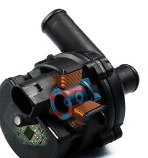
BLDC motors are now making their way into the most cost-conscious applications. For example, in the automotive sector, the use of BLDC motors is skyrocketing. Car makers are particularly attracted by the motor’s efficiency at converting electrical energy in mechanical work, which helps lower the demand on the vehicle’s power system (Figure 1). According to analyst IMS research, 600 million BLDC motors will be used in internal combustion engine-powered light vehicles by 2018 compared with 200 million units in 2011. (Larger versions of BLDC motors are already common in electric and hybrid vehicles.)

Figure 1: BLDC motors, like this unit used in a water pump, are replacing conventional motors in automotive applications (Courtesy of Melexis).
This level of interest in BLDC motors has prompted the silicon vendors to develop customized monolithic chips for the units’ electronic control systems. This article takes a closer look at BLDC motor control chips — the devices that are used to both drive the inverter bridges that ultimately energize the motor’s coils and control parameters such as speed and direction.
Reducing Hall sensor glitches
Fairchild Semiconductor has a long history of BLDC motor control that continues with the recent launch of its FCM8201 chip. The device is designed for sensored BLDC motor control. (Sensored motors require Hall effect sensors to indicate the coil position to aid the electronic commutation sequence).
The key technical advance of the FCM8201 is its choice of pulse width modulation (PWM) modes. There are two PWM modes available: sine-wave mode and the square-wave mode. The square-wave mode includes PWM-PWM and PWM-ON techniques that improve the efficiency of the motor drive.
Fairchild explains that the device also incorporates a built-in Hall signal regulation circuit that generates a 3 to 6 μs “debounce” time for each sensor signal input. This circuit reduces the glitches –– and subsequent errors –– that can occur when the transition of the Hall sensor signals is slow.
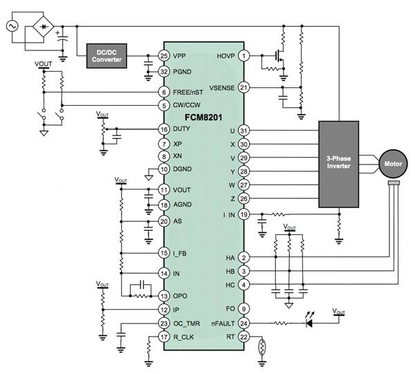
The FCM8201 can either be used in a standalone configuration without an external microcontroller (MCU), or if the designer wants to add more motor control functions than the standard device supports, and external MCU can be attached via a serial peripheral interface (SPI) interface. Figure 2 shows a typical standalone application circuit for the FCM8201. Only a few peripheral components are required to complete a BLDC motor control circuit.

Figure 2: Typical standalone application circuit for Fairchild FCM8201 BLDC motor controller.
Sensorless control using motor flux
Sensorless BLDC motors do away with Hall sensors, instead relying on the magnitude of back EMF generated when the motor turns to estimate coil position and determine the correct commutation sequence.
Sensorless control is a popular technique because it simplifies the motor’s mechanical design, but one disadvantage is that no back EMF is generated when the motor is stationary, and very little when the motor is running at low speeds. This makes it difficult for the controller to determine the position of the coils.
Targeted at low cost BLDC installations, Texas Instruments (TI) has introduced its InstaSPIN-BLDC motor control technology to address this problem. The company says InstaSPIN-BLDC is a sensorless control technique that, in field tests with over 50 different motor types, was able to get each motor up and running in less than 20 seconds. Simply put, TI describes InstaSPIN-BLDC as a software method to perform sensorless commutation on three-phase BLDC motors. According to the company, its advantages include very quick commissioning of the motor, robust control even at low speeds, and an exceptional ability to ride through velocity perturbations.
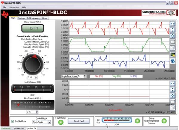
Unlike other sensorless BLDC control techniques based on back-EMF zero-cross timing, InstaSPIN-BLDC monitors the motor’s flux to determine when to commutate the motor. With the help of a free graphical user interface (GUI) (Figure 3), the user determines the flux signal in a plot window, and sets the “Flux Threshold” slider to specify at what flux level the motor should be commutated. TI says optimal commutation can be verified by observing the phase voltage and current waveforms displayed on the GUI.

Figure 3: TI’s InstaSPIN-BLDC uses a free GUI that enables the design engineer to set the flux threshold for fast motor startup.
Unlike the flux signal, the low back-EMF signal derived from a sensorless BLDC motor at lower speeds results in poor signal-to-noise (SNR) performance. The company claims InstaSPIN-BLDC enables smoother operation at low speeds, and provides more reliable motor starting, even under heavy loads.
TI offers a training module for its InstaSPIN-BLDC. The company also offers its three-phase BLDC motor kit (the DRV8312-C2-KIT) using a DRV8312/32 BLDC motor driver and Piccolo MCU with a F28035 controlCARD subsystem to run the sensorless InstaSPIN-BLDC technique. The company has published an Application Report that details how to set the system up.¹
Flexibility in design
Some manufacturers offer driver chips without integrated processors to allow designers who are familiar with a particular MCU to use that device to supervise the circuit. Alternatively, as in the case of the Fairchild chip described above, some vendors allow designers to override the internal processor by adding a more capable external MCU.
The advantages of sensored- and sensorless-BLDC motors are seeing them moving increasingly into applications that were previously dominated by conventional motors. While more expensive than the latter, this upfront expense can be offset against the lower maintenance costs and longer life of BLDC motors.
Designers looking to take advantage of these light, compact, and powerful motors will find the control system design has become much easier with the introduction of chips and design tools from major silicon vendors. There are also options that allow the designer greater flexibility in his design enhancing the opportunity to differentiate the end product from the competition.
References:
- “InstaSPIN™ BLDC Lab,” Texas Instruments, Application Report SPRABN7, November 2011.
免责声明:各个作者和/或论坛参与者在本网站发表的观点、看法和意见不代表 DigiKey 的观点、看法和意见,也不代表 DigiKey 官方政策。


 中国
中国