


Evaluating Different Approaches for Interfacing Touchscreens
投稿人:DigiKey 欧洲编辑
2013-06-27
This article looks at the latest touchscreen sensor technologies and the wide range of interfaces that the different technologies use. It also evaluates the different approaches for interfacing such sensors for human interfaces from three, four and five wire to USB, covering sensors and interfaces from Atmel, 3M, IR Touch Systems, and NKK Switches.
Resistive 4- and 5-wire touch sensors are the most popular and most common touchscreen technologies with about 75% market share, mainly due to their low costs and simple interface electronics.
The high volume of these screens requires a low-cost reliable interface, often with a low-power element. This can be provided through a range of analog features combined with low-power modes for portable, battery-powered applications.
Analog resistive touchscreens
Usually a resistive touchscreen consists of at least three layers (Figure 1). A flexible membrane made from PET film is suspended over a rigid substrate made from glass or acrylic, and both surfaces are coated with a transparent conductive film, usually Indium tin oxide (ITO). The conductive ITO layers are kept apart by an insulting spacer along the edges, and by spacer dots on the inner surface of the two ITO layers. In this way, there will be no electrical connection unless pressure is applied to the top sheet (PET film).

Figure 1: The resistive touchscreen sensor structure.
4-wire touchscreens use a single pair of electrodes called busbars on each ITO layer (Figure 2). The busbars in the top sheet and substrate are perpendicular to each other and are connected to the touchscreen controller through a 4-wire flex cable. The four wires reference X+ (left), X- (right), Y+ (top) and Y- (bottom) locations, which is key to interfacing the sensors.
An advantage of the 4-wire touchscreens is that it is possible to determine the touch pressure by measuring the contact resistance (RTouch) between the two ITO layers. RTouch decreases as the touch pressure (or the size of the depressed area) increases. This characteristic can be useful in applications in which it is not only required to detect where the pressure is applied, but also the type of pressure (area and force).
 and 5-wire (left) touchscreens")
Figure 2: Electrodes in a 4-wire (right) and 5-wire (left) touchscreens.
5-wire touchscreens have circular electrodes that sit in the ITO substrate so there is a need for a linearization pattern (conductive) to make an applied voltage gradient uniform. The four wires connect to the electrodes - these are referred to as UL (Upper Left), UR (Upper Right), LL (Lower Left), LR (Lower Right). The fifth wire is used for sensing the electrode voltage is referred to as the “sense” wire, and is embedded in the top sheet. The advantage of the 5-wire touchscreen type is that the ITO coating on the top sheet is not required to be perfect. This means that physical wearing of the 5-wire touchscreens is less critical than for 4-wire touchscreens.
The pressure points are measured by applying a voltage to the electrode pair in the resistive surface so that a uniform voltage gradient appears across the surface. A second ITO layer is necessary to do a high-resistance voltage measurement. A resistive touchscreen can thus be seen as an electrical switch requiring a small amount of pressure (0.1 – 1.5 Newton) to close.
The point of contact “divides” each layer in a series resistor network with two resistors (see Figure 2-3), and a connecting resistor between the two layers. By measuring the voltage at this point, the user gets information about the position of the contact point orthogonal to the voltage gradient. To get a complete set of coordinates, the voltage gradient must be applied once in vertical and then in horizontal direction. First, a supply voltage must be applied to one layer and a measurement of the voltage across the other layer is performed. Next, the supply is instead connected to the other layer and the opposite layer voltage is measured. In stand-by mode, one of the lines is connected to a level triggered interrupt in order to detect touch activity.
In comparison, a 5-wire touchscreen only uses the top sheet for measuring. To get a complete set of coordinates, the voltage gradient is applied on the substrate layer once in horizontal direction to determine the Y coordinate, and once in vertical direction to determine the X coordinate. In both cases, the top sheet layer is used to do a high-impedance measurement after the sensing voltage has settled. In standby mode, the fifth wire (sense) is connected to a level triggered interrupt in order to detect touch activity.
It is possible to determine the force that is applied on a 4-wire touchscreen. The first method requires a known X-plate resistance and two additional cross-panel measurements of the touchscreen. The second method requires that the X- and Y-plate resistance values are known but allows the use of a single measurement only.
Touch bouncing
Resistive touchscreens, especially the inexpensive ones, are notoriously bouncy and susceptible to glitches, and therefore filtering of the determined coordinates is necessary. Though external components can be used to implement analog filtering, this will add cost to the design. A better way to achieve correct coordinates is to run a digital filter in software: a median filter is a good choice, as it eliminates incorrect measurements. A digital filter, however, implies several measurements to get a single X or Y coordinate pair. It is also possible to introduce corrective actions by defining conditions that need to be fulfilled to accept a new set of coordinates. These include the switch back to standby mode and confirm contact before and after new measurements are taken, taking the RTouch into account. This should accept new values only if they fit in a well-defined noise window.
The end of a touch can also be detected. The error rate of the system will decrease by increasing complexity of filtering. There is an unavoidable trade-off between accurate measurements and high conversion rates. Accurate measurements require more data samples, but lower conversion rate, which may cause perceivable delays. Hence the touch system should be designed so that coordinates are generated within 50 to 100 ms.
Parasitic capacitances
The capacitive elements within the touchscreen system also need to be considered. The total capacitance can be modeled by two parallel capacitors, each with a capacitance of 50 nF or less. Together they form a time constant, which is responsible for time delays when changing the excitation of a plane. If a touch sensor is activated for the measurement by applying VCC to one of the planes, the voltage on the other (sensing) plane will immediately rise to 0.5 VCC as a result of the parasitic capacitance. Then it will settle to the voltage at the contact point by following the exponential waveform dictated by the time constant. This has to be taken into account in the development of the interface.
Touchscreen controller
A 4- or 5-wire touchscreen sensor has several key requirements for the interface. An analog-to-digital converter with a resolution of 10 bits and the absolute inaccuracy below the linearity error of the touchscreen (1.5%-3%) is required for the conversion of the analog values into digital values.
When considering the minimum detection time for applied pressure on the screen and changes in coordinates, the conversion time of the ADC must be considered. In an application that is only monitoring clicks, 70 points per seconds is typically needed. For detection of motion, e.g. handwriting, one should calculate approximately 200 points per second - taking into account that multiple measurements are included to compass the correct point (by oversampling and digital filtering). Also, the controller must be able to process the ADC readings with sufficient computational accuracy to not reduce the detection rate.
The pins driving the touchscreen must be able to sink and source in the range of 5 to 25 mA (depending on the value of the ITO resistance and the voltage used). This means that four digital IO pins and two analog inputs (ADC channels) are required. If the pins can be configured as both analog input and digital I/O, four pins are sufficient for a 4-wire touchscreen controller. A 5-wire touchscreen controller just needs one analog input line to measure the sense line.
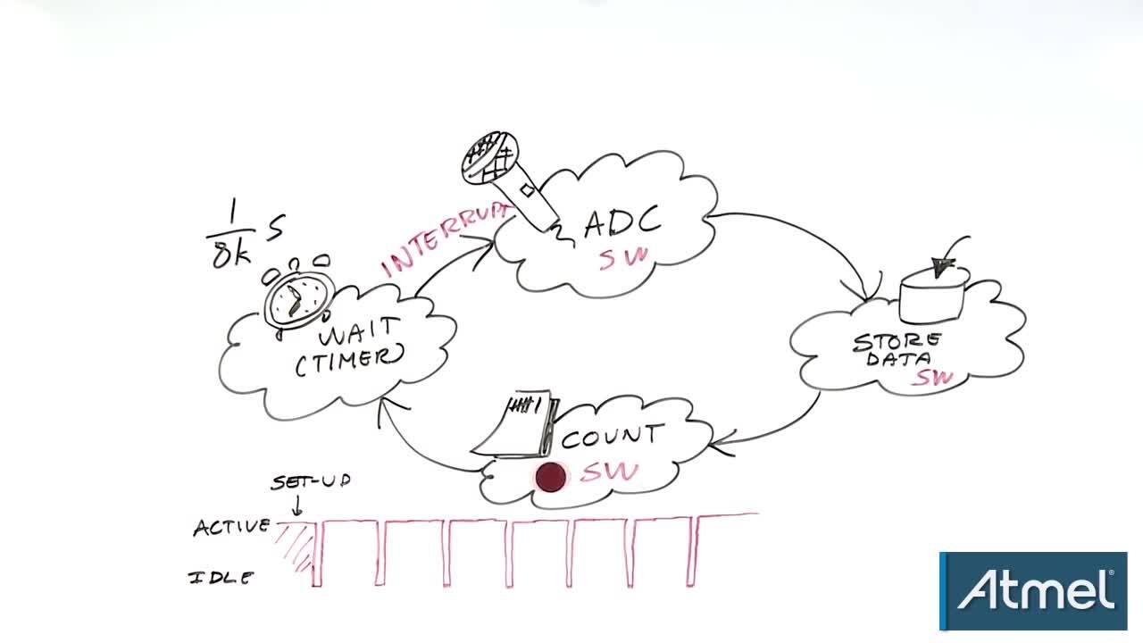
A timer is used as a scheduler for different purposes. Since the proposed method is interrupt driven, there is no need for additional delays, e.g. to debounce the touchscreen. The timer can also be used to trigger the ADC and set the I/O pins in the correct order immediately before a measurement starts. In this way, the controller powers the touchscreen only for a minimum of time. Furthermore, a timer can be used to create a timeout function, which sets the controller into sleep mode when no activity is detected on the touchscreen for a certain amount of time.
Activity detection
As touchscreens are often used in portable applications, the power consumption of the touchscreen controller should be taken into account. One way to reduce the power consumption is to let the touchscreen controller enter low-power sleep modes (“standby”) when no activity is detected on the touchscreen. To enable the use of standby operation, a level-change detection should be implemented using a pin change interrupt combined with an internal pull-up. This allows the touchscreen controller to enter low power mode while waiting for activity on the touchscreen, and wake up when the pin change is triggered.
Connecting the sensor
Devices such as the 8-bit ATmega88 can be used as a touchscreen controller. Figure 3 shows how to connect the ATmega88 to, respectively, a 5-wire and a 4-wire touchscreen. In order to drive a 5-wire touchscreen, one has to connect the sense line to an ADC channel input of the AVR. A 4-wire touchscreen needs two ADC input channels (X- and Y-). The remaining lines should be connected to any I/Os but preferably on the same port. As voltage reference, it is recommended to use AVCC with an external capacitor on the AREF pin. To minimize noise signals, particularly from the LCD display, it is common to add capacitors from the touchscreen drivers to ground forming a low-pass filter (typical value 0.01 µF), but this increases the time constant and reduces the responsiveness of the design. Sample code for handling the interface is available from microcontroller suppliers such as Atmel.

Figure 3: Design suggestion for 4-wire and 5-wire touchscreen sensor interfaces.
For example, NKK Switches’ transparent touchscreens provide options in multiple sizes, and choices of input by finger, gloved finger or stylus. Whether an application requires the 5- or 4-wire technology, the features include metal tails (analog), contact reliability with a connector, and ANR film, eliminating many of the typical visual artifacts. The film surface is non-glare and hard coated for ease of use and integrity of the surface.

Figure 4: NKK Switches resistive touchscreen.
NKK’s 5-wire touch sensors allow screens that are highly resistant to static electricity and noise pollution and provide drift-free operation despite any temperature fluctuation. A greater touch point density translates into more precision and reduction of false actuations with a quicker response time.
The sensors are aimed at applications such as medical equipment, hand-held devices, hospitality and restaurant systems and gaming.
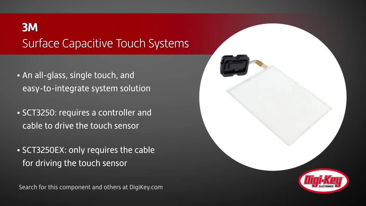
Capacitive touchscreens such as 3M’s Microtouch SCT3250EX provide an all-glass design for applications such as point of sale systems. This offers light transmission up to 11.5% better than typical resistive sensors, and 3.5% better than typical surface capacitive sensors while using coatings to protect the sensor and enhance the reliability and lifetime. A dedicated custom ASIC in the controller provides the interface to the sensor and offers industry-leading ESD protection. The EX controller's proprietary firmware and patented algorithms dynamically adapt to changes in the application’s environment to help maintain the initial video alignment of the display for the life of the product. Additionally, due to the dedicated ASIC, the SCT3250EX touch system has a "minimum touch duration" that is 50% faster than typical surface acoustic wave and surface capacitive solutions.

Figure 5: 3M’s Microtouch SCT3250EX capacitive touchscreen and EX interface controller.
This interface controller supports a point speed (PPS) of 200 pps and a minimum touch time of 5.4 ms through a USB or serial interface that uses 75 mA (typical) with a sleep current of under 500 uA.
Some screens are using infrared sensors to provide the touch data. Touchscreens from IRTouch Systems provide a USB or PS/2 interface to a PC with drivers for the Windows, Mac or Linux operating systems. These use a typical +DC 5 V supply providing +4.75 V to +5.25 V with a maximum power ripple of 200 mVrms and an operating current less than 200 mA.

Figure 6: The infrared touch sensor from IRTouch Systems.
Conclusion
Touchscreen sensors are becoming increasingly common in a wide range of applications. The basic resistive screens for embedded designs require more interfacing than the more complex capacitive or IR screens that have integrated controllers with USB or serial interfaces to a PC. There are several options for interfacing the resistive sensors depending on the type of sensor and the performance requirements, and increasingly powerful microcontrollers are able to provide a range of additional features to improve the performance of such sensors. The sample code for these devices also helps reduce the development time and enhance the performance of the overall system.
免责声明:各个作者和/或论坛参与者在本网站发表的观点、看法和意见不代表 DigiKey 的观点、看法和意见,也不代表 DigiKey 官方政策。


 中国
中国