


Flow Sensors: Calculating Volumetric Flow and Mass Flow
投稿人:电子产品
2012-03-29
Flow sensors are used to measure flow velocity, volumetric flow rate, or mass flow of a liquid or gas. Mass flow for gases is specified in units of standard liters per minute (slm) or standard cubic centimeters per minute (sccm). By referencing a volumetric flow to a standard temperature and pressure, an exact mass flow (g/min) can be calculated from volumetric flow. Figure 1 shows some examples of gas/liquid flow switches and control.

Figure 1: Gas/liquid flow control typical applications using a digital flow switch (Courtesy of SMC Corporation of America).
To design with and properly use gas/liquid sensors, we must first take some preliminary steps and also understand some terms and equations in order to get our desired design results. First, let’s look at any external support circuitry that may be needed for the sensor. Airflow sensors without an internal sensor amplifier and other circuitry sometimes require external heater control circuitry (Fig. 2), power to bias an internal sensing bridge (Fig. 3), and amplification and conditioning of the sensor output signal (Fig. 4). STMicroelectronics LM2902 op amps may be used to construct this circuit.

Figure 2: Typical heater control circuitry (Courtesy of Honeywell).

Figure 3: Typical Sensing bridge bias circuitry (Courtesy of Honeywell).

Figure 4: Typical differential amplifier circuitry for gain and/or offset to apply to the sensor output signal (Courtesy of Honeywell).
Now we can look at the main differences in mass flow in terms of volumetric flow at standard conditions, which are 760 Torr and 0°C, and volumetric flow at standard or reference conditions. Here is a typical example: 200 cm³/min (volumetric flow) of nitrogen at standard conditions of temperature and pressure calculates to 0.2498 g/min gas flow.
Definitions and equations to calculate true mass flow in g/min from volumetric flow (Q)
- P is pressure
- V is volume (cm³)
- n is number of moles of gas; R is the Gas constant 0.0821 (liters x atm/mole x degrees in Kelvin) or 82.1 (cm³ x atm/mole x degrees in Kelvin)
- T is absolute temperature in degrees Kelvin
- ρ is gas density (g/cm³)
- M is mass in grams (g)
- m is mass flow (g/min)
- Q is volumetric flow
- QS is volumetric flow at standard conditions (sccm)
 (Equation 1)
 Gas density is defined as:
 (Equation 2)
 Now substitute Equation 1 into Equation 2 and get gas density:
 (Equation 3)
 Mass flow is defined as density x volumetric flow rate:
 (Equation 4)
 Now redefine mass flow using gas density as derived from the Ideal Gas Law. Substitute Equation 3 into Equation 4 and get Mass flow:
 (Equation 5)
 How to calculate volumetric flow (Q) using true mass flow (g/min)
Mass flow sensors such as Honeywell’s AWM3100V microbridge sensors (as opposed to volumetric sensors) will give the same output voltage even if there are temperature or pressure changes. Since these devices sense mass flow, confusion may result when mass flow sensors are used with volumetric devices such as rotameters or pith-ball indicators (as seen on oxygen tanks or the blood pressure sphygmomanometer in your doctor’s office). See the “Definitions” section at the end of this article for a more complete explanation of what a rotameter is.
Accurate mass flow calculations for volumetric devices require consideration of both temperature and pressure ranges. These volumetric devices will exhibit different flow rates at varying temperatures than the microbridge sensor based on mass flow. Let’s do some simple calculations to show the relationship between mass flow and “non-standard” volumetric flow.
An example using the Honeywell AMV3100 with a mass flow rate of 0.2498 g/min (or 200 sccm) at the same pressure of 760 Torr (1.0 atm) but at a different temperature, 25°C, has a 5 VDC output voltage, indicating a standard flow rate (QS) of 200 sccm. The rotameter, however, would indicate a non-standard volumetric flow rate (Q).
We can use Equation 5 to re-arrange the formula for the volumetric flow value to calculate the rotameter non-standard volumetric flow rate. We get this result:
 (Equation 6)
 So let’s use the following values to calculate volumetric flow rate (Q). Multiply the R value by 1,000 to convert the number to cm³:
m = 0.2498 (g/min)
m = 28.0134 grams in 1 mole of N2
n = 1 mole
P = 1.000 atm (760 Torr)
R = 82.1 (cm³ x 1 atm)/(mole x °K)
T = 273.13°K (0°C) + 25°C = 298.13 x °K
Q = 218.26 cm³/min
So we have shown that QS, the standard volumetric flow rate, is 200 cm³/min but Q, the nonstandard volumetric flow rate, is 218.23 cm³/min.
How to calculate volumetric flow (QX) using “standard” volumetric flow (QS)
Nonstandard volumetric flow can be found using the ratio of temperature and pressure at referenced conditions (760 Torr and 0°C) versus “X” conditions of temperature and pressure. This method eliminates the need to use gas density values at reference conditions (760 Torr and 0°C) versus “X” conditions of temperature and pressure.
Some definitions:
QX is volumetric flow at X conditions of pressure and temperature
QS is volumetric flow at standard conditions of 760 Torr (1 atm) and 0°C
TX is temperature at “X” conditions in °Kelvin (°K)
TS is temperature at standard conditions in °Kelvin (°K)
PX is pressure at “X” conditions in °Kelvin (°K)
PS is pressure at standard conditions in °Kelvin (°K)
If we assume that mass flow is held constant over temperature and pressure, then the following relationship is true:
ms = mx
That is:
ms mass flow, at standard conditions is equal to mx mass flow at nonstandard X conditions of temperature and pressure.
Therefore:

Solving for QX yields:
 (Equation 7)
 Using Equation 7 we can calculate volumetric flow (QX) at “X” conditions from volumetric flow (QS) at reference conditions of 760 Torr and 0°C:
Given values of
QS = 200 sccm
PS = 1 Torr or 1 atm
PX = 1 Torr or 1 atm
TS = 273.13°K (0°C)
TX = 298.13 °K or 25°C
So QX = QS x (PS/PX) x (TX/TS) = 218.3 cm³/min.
Applications of gas/fluid flow sensors
Some primary and critical area usages of gas/fluid flow sensors are in the medical industry. One great example is the anesthesia machine which is designed to deliver drugs to a patient in order to eliminate pain or other unwanted sensations. Obviously, this can be a very life-critical application requiring an accurate and constant flow of medical gases (e.g., air, oxygen and nitrous oxide) combined with a very accurate concentration of anesthetic vapor (such as isoflurane) under a constant desired pressure and flow rate (Fig. 5).

Figure 5: Anesthesia delivery machine. (Courtesy of Honeywell.)
Honeywell has a variety of flow sensor solutions that can be used in such a machine to control pressure, air/gas flow and temperature. We will focus primarily on the airflow sensors here.
Flow sensors are common in Ventricular Assist Devices (VAD). The VAD is a mechanical pump assisting the heart by pumping blood to the rest of the body for patients with congestive heart failure. The VAD is typically made up of three sections (Fig. 6):
- The pump: May be placed inside or outside the body and is connected to the heart via a tube. Blood will travel from the heart, like in a healthy heart, down the inflow tube into the VAD. The VAD performs the heart function of pumping the blood to an outflow tube to a major blood vessel on its way back to the heart.
- The controller: This device is usually placed outside the body and controls the VAD by measuring airflow to be sure the correct amount is delivered to the pump that drives the flow of blood through the heart.
- The energy source: Again, this is typically outside the body and is either an AC power adapter or a battery pack to power the pump.

Figure 6: A ventricular assist device. (Courtesy of Honeywell.)
For those designs that just need a drop-in, all inclusive solution and not external custom design, the designer can choose a sensor such as Honeywell’s Zephyr HAF series with a digital series bus output that can connect right to a microcontroller are expertly designed to measure the flow of air, oxygen, and nitrous oxide.
The ventilator is another life-critical device (Figure 7). This system measures the flow of air, oxygen, and nitrous oxide so that a specific balanced mixture, set by physicians, gets administered to the patient. The air and oxygen flow sensors generate signals to help the microprocessor control the valves to deliver the desired inspiratory air and oxygen flows.

Figure 7: The ventilator (Courtesy of Honeywell).
A number of control design strategies may be appropriate for the control of the air and oxygen flow delivery valves. The microprocessor performs multiple operations including sampling the pressure signals, computing a desired airway pressure and total inspiratory flow level, and actuating the air and oxygen valves for each individual inspiratory cycle. To achieve these operations efficiently and in real-time, a high-speed, low-power, highly-integrated microprocessor is needed. DSPs can be used for such demanding control applications.
Some systems are equipped with compressed-gas tanks and backup batteries to provide ventilation in case of power failure or defective gas supplies.
The CPAP machine is another air flow-based device. Continuous positive airway pressure (CPAP) is a method of respiratory ventilation used mainly for the treatments of sleep apnea at home. The air and flow sensors generate signals to help the microprocessor regulate the motor to adjust/maintain the desired pressure as the person inhales or exhales.
The microprocessor performs multiple operations including sampling the pressure signals and computing a desired airway pressure and flow level to communicate with the motor. To achieve these operations efficiently and in real-time, a high-speed, low-power, highly-integrated microprocessor should be used. A high-quality DSP can be used for such applications and will also provide the patient with an ultra-quiet operation.
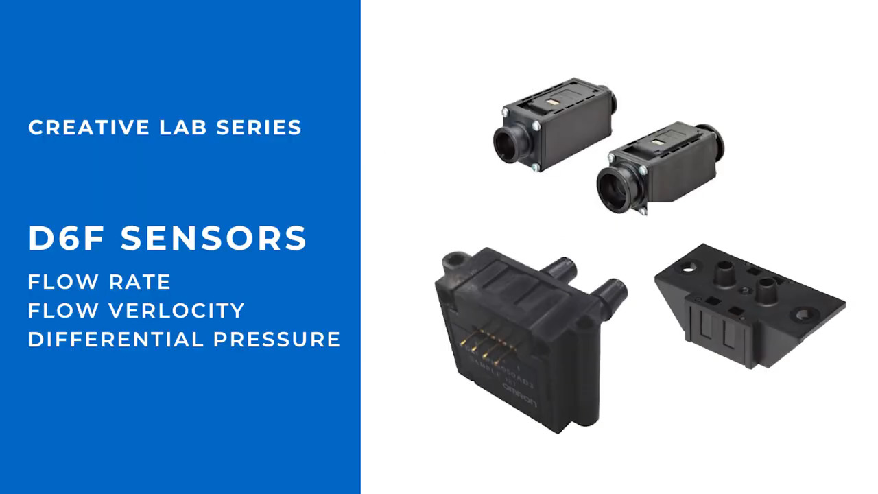
Omron Electronics, EMC Division has the D6F-P air flow sensor for use in ventilators, CPAP systems, and anesthesia machines. Important features that are built in include a dust segregation system (DSS), built-in voltage regulator, temperature compensation, and amplified voltage output. This output can be sent to a signal conditioning amplifier on to a discrete A/D converter or an A/D on a microcontroller.
Cynergy³ Components has a line of flow switches, including the FS22A, which are reed-based. These devices have an “operate flow rate” above which the switch is activated and a “release flow rate” at which the switch will open. The reed switch can switch 240 Vac or 120 Vdc at 15 VA.
Summary
Using the various types of gas/liquid flow devices and the equations given above, we can design anything from an industrial product flow inside a factory to patient life support and comfort devices used in a hospital. The designer must choose the right devices for the overall project needs by carefully reviewing manufacturer data sheets and application notes, and understanding how to calculate ultimate critical parameters of gas or fluid flow.
Definitions
Rotameter or pith-ball indicator: The rotameter, or pith-ball indicator, is an industrial flow meter used to measure the flow rate of liquids and gases. The rotameter consists of a tube and float. The float response to flow rate changes is linear. The rotameter's operation is based on the variable area principle: fluid flow raises a float in a tapered tube, increasing the area for passage of the fluid. The greater the flow, the higher the float is raised. The height of the float is directly proportional to the flow rate.
References
- Honeywell application note, “Mass Flow Versus Volumetric Flow.”
- Honeywell application note, “Sensors in Anesthesia Machine Applications.”
免责声明:各个作者和/或论坛参与者在本网站发表的观点、看法和意见不代表 DigiKey 的观点、看法和意见,也不代表 DigiKey 官方政策。


 中国
中国