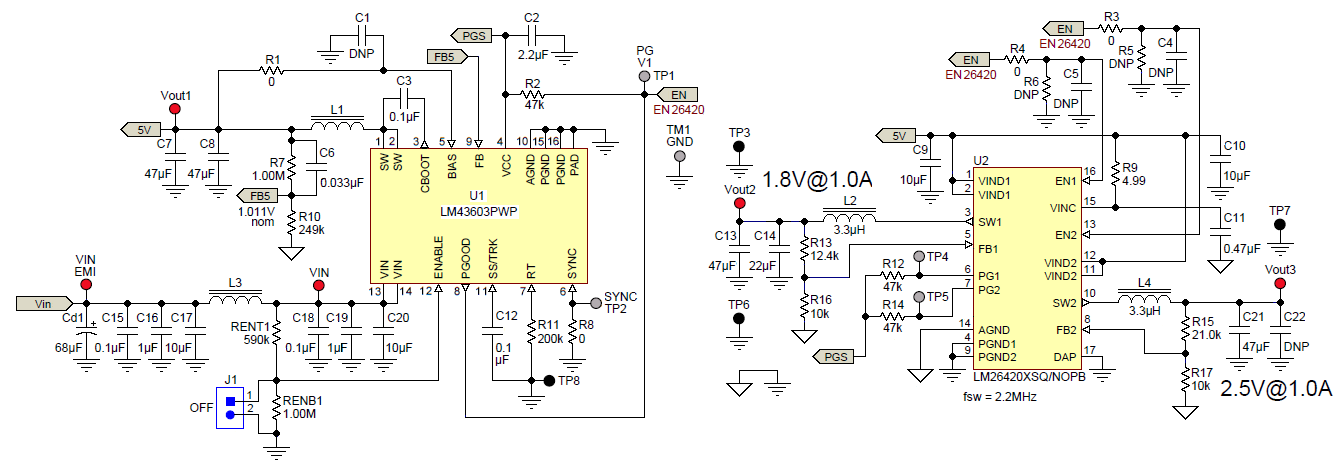
The reference design PMP9462 is a single input step-down converter with three low-noise outputs. The module uses LM43603, a synchronous step-down DC-DC converter capable of driving up to 3A of load current from an input voltage ranging 7V to 36V. The 5V output from LM43603 enables the LM26420 which further steps down this voltage to produce 1.8V and 2.5V outputs, capable of driving 1A load curren…
The PMP9483 reference design is a very-tightly laid-out triple-output power supply design featuring the new LM43603 36-Volt, 3-Amp synchronous SIMPLE SWITCHER converter, and two LMZ10501 nano modules. The LM43603 is taking a wide input voltage of up to 36 Volts and converting it down to 5 Volts, and then the LMZ10501s are converting that 5 Volts down to 1.8 Volts and 2.5 Volts, all in a very smal…
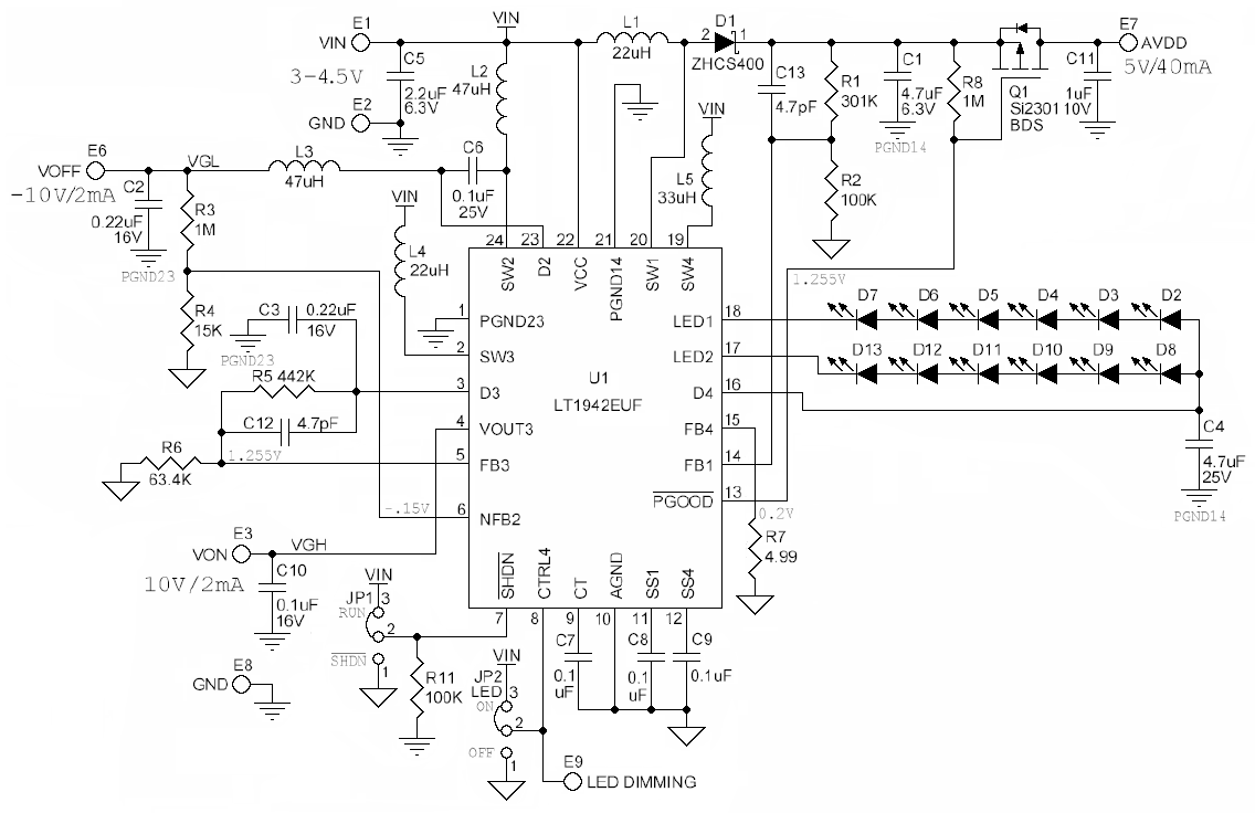
Demonstration Circuit DC688 is a quad output power supply intended for use in small to medium size TFT panels. The circuit features the LT1942 quad output switching regulator and generates an LED driver along with the triple output supply required for the TFT panels.
The ADP2114 evaluation (demo) board is a complete, dual, step-down, dc-to-dc converter design based on the ADP2114, a configurable, dual 2 A/single 4 A, synchronous step-down, DC-to-DC regulator.
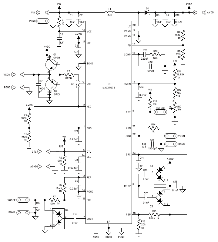
The MAX17075 evaluation kit (EV kit) is a fully assembled and tested surface-mount circuit board that provides the voltages and features required for active matrix thin-film transistor (TFT), liquid-crystal display (LCD) panels in LCD monitors and LCD TVs. The EV kit contains a step-up switching regulator, a two-stage positive charge pump for the TFT gate-on supply, a single-stage negative charge…
The MAX17521 evaluation kit (EV kit) provides a proven design to evaluate the MAX17521 dual high-efficiency, high-voltage, synchronous step-down DC-DC converter. The EV kit generates 3.3V and 5V output voltages at load currents up to 1A from a 7V to 60V input supply.
Demonstration circuit 1811B-B is a dual-output, high efficiency, high density, μModule® regulator with 4.5V to 17V input range. Each output can supply 13A maximum load current. The demo board has a LTM®4676A μModule regulator, which is a dual 13A or single 26A step-down regulator with PMBus power system management. Please see LTM4676A data sheet for more detailed information.
Demonstration Circuit 1582B featuring the LTC3108 is a highly integrated DC/DC converter optimized for harvesting and managing energy from extremely low input voltage sources such as thermoelectric generators (TEG). The step-up topology operates from input voltages as low as 20mV.
An isolated bias supply is implemented in this evaluation board with LM5017 Constant-On-Time regulator. LM5017 regulator integrates both the high- and low-side power switches essential for creating isolated buck converter.
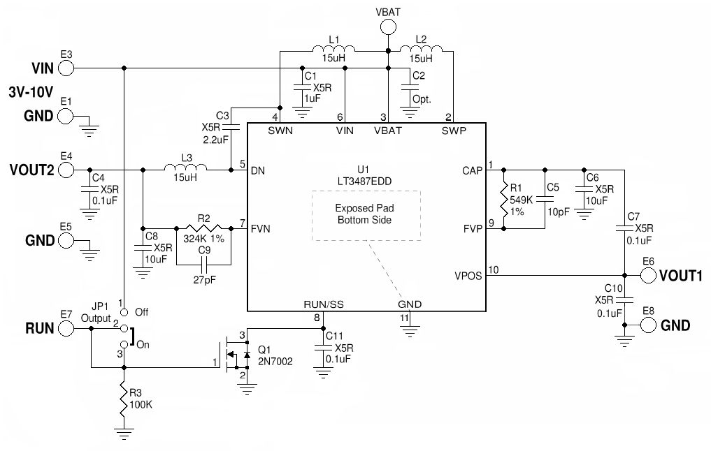
Demonstration circuit 912 features the LT®3487EDD. The demo circuit demonstrates small size and low component count in a Boost Circuit and an Inverting Circuit. The Boost Converter is designed to convert a 3V-5V input to 15V output at 45mA-90mA maximum load. The Inverting Circuit generates a -8V output at 90mA-150mA maximum load from the same input. Since the maximum Vin of the LT3487EDD is 16V, …


 中国
中国